

Drawings and documents
National Archives restored drawings: drawing
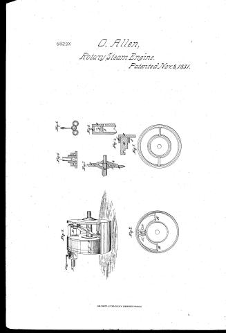
Oliver Allen's Patent Drawing for a Rotary Steam Engine and Pump

National Archives, Restored Patent Drawings (Record Group 241) · Full-size scan at the National Archives · Catalog record
Show the text on the drawing Hide (60 words)
Words on the drawing as machine-read by the National Archives; not checked. Useful mainly for searching.
121. STEAM. / 1. ENGINES. / [150] Rotary. / S.A. / $2- / CLASSIFICATION / Concentric-Piston. / 6829-X / OLIVER ALLEN'S, / DIVISION. / ROTARY STEAM ENGINE AND PUMP. / Rotary Pumps 46y d Patented 8 nov / hour'1831 / F'zg / F'ig 5 / is / 7'ig 6 / I', / I's / 7. / Ing3 / PQ / I', / NIO / Fig2 / of / Fig 3 / II / IVE / NE
USPTO scan
The patent as scanned by the USPTO
-
 Page 1
-
 Page 2


U.S. Patent and Trademark Office · Google Patents
Show the transcription Hide (424 words)
Machine transcription (LightOnOCR) of the pages as scanned by the USPTO, most of them the handwritten copies made when the records were restored after the 1836 fire. Not checked; it can misread handwriting, so compare it with the scan.
Page 1.
6829X
O. Allen,
Rotary Steam Engine.
Patented Nov. 8, 1831.

AM. PHOTO-LITHO. CO. N.Y. (OSBORNE'S PROCESS)
Page 2.
Mar 8 1831 6829X 577.
Oliver Allen, Norwich, Connecticut
Letters Patent.
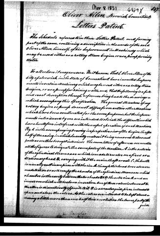
The Schedule referred to in their Letters Patent, and forming part of the same, containing a description in the words of the said Oliver Allen, himself, of his Improvement in Machinery which may be used either as a rotary steam engine or as a pump for raising water.
To all whom it may concern. Be it known, that I, Oliver Allen of the city of Norwich, in the state of Connecticut, have invented Improvements in certain Machinery which may be used either as a rotary steam engine, or as a pump for raising water, and, that the following is a full and exact description thereof, reference being had to the drawings which accompany this Specification. The general structure of my rotary engine or pump does not differ from certain other Machines which have been constructed for the same purposes; but the Improvements introduced by me are intended to obviate the difficulties which have heretofore interfered with the useful operation of such Machines. Fig. 1. in the accompanying drawing is a perspective view of the engine, the upper half of the casing in which is usually enclosed it being removed to show such parts as are thus brought into view. The same letters of reference are used in all the figures to designate the same parts of the Machine. A is the exterior of the cylindrical steam case which is made to revolve on a fixed or stationary head B, carrying with it the main shaft or axle C. The head D is usually cast in one piece with the rim A. Through this head two valves are made to slide so as to occupy the chamber of the cylindrical steam case which chamber is the cavity between the two heads B D the outer rim A, and an inner one which will be shown in section. One of these valves is shown at E, the other is diametrically opposite to it. E is a conical guide piece intended to open and close the valves. As the valves are intended to be kept closed during a little more than one half their revolution the lower part of the guide
Published accounts: journal notice
Notice in the monthly list of patents, with remarks
Journal of the Franklin Institute, new ser., vol. 9 (1832), p. 315 · View the page
13. For an improved Rotary Steam Engine, or Pump; Oliver Allen, Norwich, Norwich county, Connecticut, November 8.
Remarks. The attempts at rotary steam engines have been so numerous, that it is scarcely to be expected that any other than new modifications, and methods of obviating the difficulties which have attended their use, should be now brought forward. The present engine, in its general structure, resembles others which have been previously patented, and this is stated by the patentee. There is to be a revolving drum, with a stationary head. Valves are opened and closed by a circular guide piece, so curved as to effect this object in the desired manner. One of the improvements proposed is the making depressions in the head of the revolving drum, or cylinder, over which depressions the edges of the valves pass; these allow the steam to escape at the moment the valve begins to rise, and thus relieve it from the pressure which would impede its opening. Another part claimed as an improvement is the employment of three cocks in a steam box, the keys of which cocks are geared together, so that one lever acts upon the whole; these cocks serve to cut the steam off, or to admit it at either of two openings, so as to stop or reverse the motion of the engine. The following claim notices these and other parts viewed as new. "1st. The manner of fixing and adjusting the circular guide plate for opening and closing the valves. 2nd. The excavations made in the fixed head for relieving the valves from the pressure of the steam before they commence rising. 3d. The mode of giving a lateral adjustment to the cylinder by means of the circular plates inserted into the ends of the casing, and which bear upon theshoulders of the shaft. 4th. The employment of, and the manner of fixing the three cocks for the admission and discharge of steam, when used as a steam engine. 5th. The packing in the grooves of the fixed head, by means of circular metallic rings, borne up by elastic packing, or by springs."
About this record
- Patentee
- Jim Shaw's X-patent list
- Date
- the Name and Date index of patents, USPTO records, Jim Shaw's X-patent list
- Invention
- the Name and Date index of patents
- Listed in
- the Name and Date index of patents, USPTO records, Jim Shaw's X-patent list, the Journal of the Franklin Institute, Burke's List of Patents (1847)
- Burke's 1847 Patent Office list gives the same patent.