

Drawings and documents
National Archives restored drawings: drawing
John and Charles Bruce's Machine for Manufacturing Crackers


National Archives, Restored Patent Drawings (Record Group 241) · Full-size scan at the National Archives · Catalog record
Show the text on the drawing Hide (370 words)
Words on the drawing as machine-read by the National Archives; not checked. Useful mainly for searching.
Sheet 1. 65.2 KITCHEN UTENSILS 3) Bread and Crack / chines / L6] Cracker Mach's / $20 / so / John Stampels and Charles Bruce's / 6963-4 / CCCCC / Cream / DIVISION. / Machine for manufacturing Cuchers & / foregoing Specification. the BB the frame C.C. and C.C the tworbacky having teeth there / Pio 8. represents a perspective view of the Machine first Ocerbed in the / drieal D Cutting bylinder the withlits Cullers in is. EEE the three Cyline / Cough is Compressed. / rollers поед to dough FFFF the Vitalfam on / mar 1332 / Fid: b. / saropers / I' / I' / LA / Fig / 2. / BABA / Fis. 2. is @ Pertical Section of So much y of oTe of the described Machines / as IS w neeefsary to whibit the arrang ement of revolving yearly pulley or wheely / which comer them togethert excepted. / chine before mentioned B the Cutting Cylunder. C.C.C three tope rollers. / AAAA The four of lundrical rollers described as comprieing the second ma / D.D.D. the Maby to Sprevent the Dough from falling Small rollers might have been / made to occupu their yelaed E.F the hopper at which the cough is yout in. / G. the inclined plane H.I.K.L. the feeding cloth Commonly Called and rollers around / which to carry off the dough The Jullies wheels Ho / giving movement to these are not sheard, they Can however easily be conceived
Sheet 2. 65. KITCHEN UTENSILS. / Stampe / CLASSIFICATION / [6] 6 Cracker Mach's / (65) KITCHEN UTENSILS. / (6) Bread and Cracker Machines / John & Charles Bruci's / 6963 X / DIVISION. / References, / #6963x / Machine for Manufacturing Crackers &cm / Patented 13"March 1832. / Fig.3.B, section of Cutting Cylinder / Renewed by Congreps / short cylindrical or other shaped tubes / b'b'd'sc. cylindrical or other shaped wires / Fig:3. / Tubry22 1847. / set in tubes a'a'kc; for portorating / biscuits / enlargement / d' / d'd'. Kc: central wires with heads. / supporting plates é,e,é,pe, with / perforations made in theme to / let the wires b'b'b',pass through. / f.f.f, &: spiral springs by / a' / the action ofwhich the biscuits / are expelled ,&c / d' / J.L. Witnefsed Smith / as to John Bruce / a. The Smith / (signes) / John Pruce / Richart Sauton / to Charly Bruco / Charles Pruce / Cohn J.Bruee / as
USPTO scan
The patent as scanned by the USPTO
-
 Page 1
-
 Page 2
-
 Page 3
-
 Page 4
-
 Page 5
-
 Page 6
-
 Page 7
-
 Page 8
-
 Page 9
-
 Page 10


U.S. Patent and Trademark Office · Google Patents
Show the transcription Hide (3,060 words)
Machine transcription (LightOnOCR) of the pages as scanned by the USPTO, most of them the handwritten copies made when the records were restored after the 1836 fire. Not checked; it can misread handwriting, so compare it with the scan.
Page 1.
No Printed Specification Available
6963X
J. H. C. Bruce,
Cracker Machine,
Patented Mar. 13, 1832.
Sheet 1-2 Sheets.
Fig. 1.
Fig. 2.
M. PETERS, PHOTO-LITHOGRAPHER, WASHINGTON, D. C.
Page 2.
Sheet 2 of 2 Sheets.
6963X
J. & C. Bruce,
Cracker Machine,
Patented Mar. 13, 1832
Fig. 2
Witnesses:
J. L. Smith
Wm. H. Smith
Richard Paulson
John D. Bruce
Inventors:
John Bruce
Charles Bruce
H. P. LEE, PHOTO-LITHOGRAPHER, WASHINGTON, D. C.
Page 3.
John Bruce and Charles Bruce.
Letters Patent.
The schedule referred to in these Letters Patent and making part of the same, containing a description in the words of the said John Bruce and Charles Bruce of their improvements in the machine for manufacturing ship biscuit, pilot bread, crackers &c.
Know all whom it may concern by these presents, that we John Bruce of the County of Kings and Charles Bruce of the same County & State of New York, have invented and discovered a new and useful machine for manufacturing or forming from the dough of flour and other usual materials, what is commonly called ship biscuit, tarry and pilot bread crackers, ship peas cakes, ginger nuts, tea biscuit &c. &c. and that a specification of the aforesaid machine is contained in the words following. It is a rectangular slab of suitable length, width and thickness on a made of wood or other material or materials is to be provided having its two longest surfaces perfectly plane or level & parallel with each other. A piece of framework is to be prepared among other things, to receive this in such a manner that its two largest surfaces maybe parallel with the horizon or as near thereon as maybe convenient and in such manner also that with the aid of grooves or grooves or other similar contrivances made in or attached to the said frame, it maybe moved backward and forward in the direction of its length a sufficient and convenient distance. The use of this slab is to receive at one end of it and on the uppermost surface of the same, the dough from which is intended to be made the aforesaid ship biscuit, tarry and pilot bread, crackers, ship peas cakes, ginger nuts, tea biscuit &c. &c. and being put in motion by any convenient power what soever to convey the said dough underneath two, three or more cylindrical rollers placed one above the other on the said slab, with their axes parallel to each other and parallel also to the said slab but one end in question nearer
Page 4.
nearer to the said slab as they are located farther from that end of the frame first receiving the dough. The dough being thus conveyed on the said slab, underneath the said rollers is pressed into a flat form and spread evenly over and upon its surface every time it passes under any one of the said rollers becoming thinner than it was before till having passed under that roller which is farthest from that end of the frame which first receives the dough it is brought as near as may be to the intended thickness of the aforesaid slip biscuit, navy biscuit, bread, crackers, New York cakes, ginger nuts, to a biscuit &c. &c. A slite for this use of this slab, is after having in conjunction with the rollers already mentioned, pressed or spread the dough into its flat and proper form and thickness, to convey it under the cylinder hereafter and herein to be described and named the cutting cylinder for the purpose of being cut into pieces of the required shape and such as we have already mentioned. Effectually to make the said rectangular slab serve the purpose required of it, it is necessary that, to one or both vertical sides of the said slab should be attached to what is usually called a rack with teeth on its upper side working into teeth of a wheel fastened and belonging (in preference) to that particular cylindrical roller, which is nearest to that end of said frame, which first receives the dough, and in order to keep the dough from spreading sideways so as to encroach upon said flits the teeth of the said rack as also the teeth of the wheel into which it works a strip of any suitable material, and of sufficient height, is to be made fast in the uppermost surface of the said slab in such a manner as to be in the direction of its length at or near each edge of the said slab, and extending the whole or nearly the whole length thereof; Motion backward and forward will be alternately given to the aforesaid slab, by the use of a crank or other machine attached to the shaft of the cylindrical roller last mentioned and moved by the hand or other conveniently regulated power in an alternate manner, the cylindrical rollers two, three, four, or more, of them are seen in the frame which receives and contains the aforesaid slab they are placed over it in such manner that their axes are at right angles to the length of the slab, and by means or any other convenient machinery they are made capable of being elevated or depressed so as to raise
Page 5.
69103x Mar. 13, 1832
further from or approach nearer to the upper surface of the said slab, as occasion may require, a wheel (and it has been already referred to) is attached to the shaft of that particular cylindrical roller, which is nearest to that end of the aforesaid frame at which the dough is first received and works into the teeth of the rack immediately below it, giving motion to it, and of course to the slab itself to which it is permanently secured in a backward and forward manner.
But if the wheel first herein to be made fast to the shaft of the particular cylindrical roller, above named the shaft of no other cylindrical rollers have any wheel attached to it, all other rollers will be moved by the mere contact and pressure of the dough between them and the slab. It will be understood also that the two strips intended to prevent the dough from encroaching upon the rack or racks above mentioned will require that all the cylindrical rollers be so shaped as to admit the said strips to pass freely under them. They will or rather should be so shaped accordingly. The piece of machinery intended to be made use of in cutting the dough into the desired forms after it shall have been rendered flat and of an equal and proper thickness is a cylinder which we shall name the cutting cylinder supplied with what we shall call cutters. Like the cylindrical rollers already mentioned for flattening the dough it stands over or above the aforesaid slab, but in such manner as to permanently on it, and having its axis or axiswise, or at right angles to the direction of the length of the slab; it is situated, in the frame of either from that end of it at which the dough is first received than any of the cylindrical rollers above mentioned, and of course nearest as may be to the one which brings the said dough to the desired thickness. The cutters if not made of a piece with the cylinder itself, as they maybe, tho not perhaps with the same convenience as in another manner, are inserted into the main cylinder by the aid of screwwork, or otherwise, if the inner end be to be of a circular shape circular holes of suitable diameter may be milled or bored at right angles to the axis, into the cutting cylinder, so as to penetrate into its interior the said cutting cylinder of course being hollow and either with or without the ends of the same being closed at the pleasure of the owner, but then later
Page 6.
holes or perforations are secured or otherwise made fast short cylindrical tubes having an internal diameter equal to that which the biscuit be. is intended to pass. That extremity of each cylindrical tube which may be called the bottom, and which is nearest in point of distance to the axis of the aforesaid cutting cylinder has its opposite closed up with a plate either separately attached or of a piece with the tube itself. The length of each of these short cylindrical tubes should not be less than three, four, or six times the thickness of the proposed biscuit. Into every such plate when the biscuit be. is required to be p. these should be inserted and made fast thereto as many cylindrical or other shaped wires as may be necessary to perforate the biscuit be. sufficiently, these wires should be made somewhat sharp and pointed, they should be placed as near as may be equi distant from each other, and their external extremities should terminate in the external surface of the aforesaid cutting cylinder; In the center of the plate which closes the bottom of each of the short cylindrical tubes is inserted but in a loose and not permanent manner, another cylindrical or other shaped wire and which will call the central wire, standing at right angles to the axis of the aforesaid cutting cylinder, having an enlargement, head or nut on that extremity of it which appears within the cavity and being of such a length that the other extremity terminates in the external surface of the said cutting cylinder. To the external extremity is secured in a permanent manner a circular plate not flat but curved to the periphery of the aforesaid cutting cylinder of a diameter nearly equal to that of the tube in which it is located and having as many perforations made in it as there are cylindrical or other shaped wires as already mentioned made into the plate in the extremity of the tube opposite to it, these perforations being somewhat larger than the wires which pass through them. Between the two plates in the two opposite extremities of each of the short cylindrical tubes above mentioned one made fast to the said tube the other moveable in it, is a spiral or other spring or springs the intention of which is to allow the outermost and moveable plate, as the trough is pressed into the tube to rise or retreat from before it, and when the cutting cylinder
Page 7.
cylinder shall have turned sufficiently to admit of it, to eject the biscuit to be before mentioned from the tube already perforated and fit to be put into the oven. The use of the enlargement head or nut on the internal extremity of the aforesaid benthial wire is to prevent the external and movable plate to which it is attached from falling out of its tube, when it is in a declining or pendant position. It need scarcely be added that the external surface of the last mentioned plate may have any number of devices or grooves or other wise made upon it that may be desired, and this will be the more easily effected in the working those articles the dough of which does not require to be perforated, for in this case no wires will be working in any of the short cylindrical tubes except the central wire and of course no perforation whatever in the movable plate. The short cylindrical tubes in order to enable the operator to obtain the greatest number of pieces of biscuit from a given quantity of dough should be arranged in longitudinal series in such manner that the individual tubes of any two contiguous series should not be opposite to, but equally intermediate between those of each other, the distance apart of these tubes in every direction being the least possible that circumstances will admit. In using the machine as thus far described and which is complete, the dough is placed upon the slab after the slab itself as well as the remaining machinery have been dusted with flour to prevent its sticking, the roller nearest to the dough is set in motion by a crank or any other means, this carries the slab with the dough upon it underneath the said roller, and the motion being so continued underneath another and another until it be sufficiently flattened where the motion being still continued the dough is carried under the cutting cylinders, enters the short cylindrical tubes aforesaid pressing inward the movable plates before described and dividing the biscuit to be, by the action of the spiral springs so soon as the cutting cylinder shall have turned so far from the aforesaid slab as to admit of it. When the whole plate of dough shall have passed under the said cutting cylinders and a proper distance beyond it, the biscuit to be are to be passed to the oven, the remainder or pieces among the dough the slab is turned back to its former position.
Page 8.
position and the same process repeated. Perhaps a still better method of constructing a machine embracing the same principles will be as follows. Let there be provided a suitable frame of wood or other material in which are to be secured, so that they may be capable of revolving when applied to use four or more cylindrical rollers of the same length as the aforesaid cutting cylinder of convenient, and better probably than otherwise, of one and the same diameter. Let the axis of these be so placed that the upper surface shall be in one and the same horizontal plane, and let this plane, as near as may be convenient, be coincident with the horizontal plane of the aforesaid frame;
The three or more cylindrical rollers first above mentioned in this one specification together with what we have denominated the cutting cylinder are placed immediately over the said four cylindrical rollers just in the present modification described and at the same distances therefrom as they were directed to be from the rectangular slab aforesaid; and of the four last mentioned cylindrical rollers, to wit, that over which is placed the cutting cylinder aforesaid may have its external curved surface composed of some suitable elastic covering for the purpose of enabling the short cylindrical cutting tubes more effectively to perform their duty than they otherwise might.
To obtain the proper proportionate velocities of these various cylinders &c. let appropriate pulleys or wheel work be made use of to connect each of the machinery as required, and let also stationary slabs or planes of wood or other suitable material or small revolving rollers be placed between each successive pair of cylindrical rollers to support the dough from falling while it is being conducted to the next pair, and the operation may probably be better done than by the machine first and herein described. At that end of the frame at which the dough is received a conveniently inclined table or hopper should be provided and made fast to the same frame the use of which table or hopper is to introduce the dough into the
Page 9.
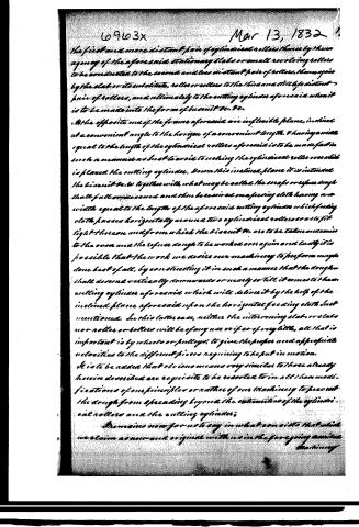
The first and more distant pair of cylindrical rollers, thence by the agency of the aforesaid stationary slab or small revolving rollers to be conducted to the second and less distant pair of rollers, thence again by the slab or its substitute, roller or rollers to the third and still less distant pair of rollers, and ultimately to the cutting cylinder aforesaid when it is to be made into the form of biscuit &c. &c.
At the opposite end of the frame aforesaid are inflexible planes, inclined at a convenient angle to the horizon of a convenient length, & having a width equal to the length of the cylindrical rollers aforesaid is to be made fast in such a manner as best to avoid touching the cylindrical rollers over which is placed the cutting cylinder. Down this inclined plane it is intended the biscuit &c. together with what may be called the scraps or refuse dough shall fall or be saved and then be received on a feeding cloth having a width equal to the length of the aforesaid cutting cylinder which feeding cloth passes horizontally around two cylindrical rollers or as so fit tight thereon and from which the biscuit &c. are to be taken or carried to the oven and the refuse dough to be worked over again and lastly it is possible that the work we desire our machinery to perform may be done best of all, by constructing it in such a manner that the dough shall descend vertically downwards or nearly so till it comes to the cutting cylinder aforesaid which will deliver it by the help of the inclined plane aforesaid upon the horizontal feeding cloth last mentioned. In this latter case, neither the intervening slab or slabs nor roller or rollers will be of any use or if so of very little, all that is important is by wheels or pulleys, to give the proper and appropriate velocities to the different pieces requiring to be put in motion.
It is to be added that obvious means very similar to those already herein described are requisite to be resorted to in all the modifications of our principles or rather of our machinery to prevent the dough from spreading beyond the extensions of the cylindrical rollers and the cutting cylinder.
It remains now for us to say in what consists that which we claim as new and original with us in the foregoing article.
Page 10.
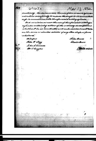
Machinery. We claim as new, the use of two or more cylindrical cut rollers successively to reduce the dough to its desired thickness in connection with the aforesaid cutting cylinder.
And we claim as new the use of the aforesaid cutting cylinder containing cutters of the ordinary description, whether it be so constructed as to make incisions in it or on the same or similar articles of any other shape or form whatever.
Witnesses
Peter P. Stagg
John S. Cameron
M. J. Ruggles
John Bruce
Charles Bruce
Filed Nov 20, 1832
Published accounts: journal notice
Notice in the monthly list of patents, with remarks
Journal of the Franklin Institute, new ser., vol. 10 (1832), p. 160 · View the page
13. For a machine for Making Crackers, Ship Bread, &c.; John Bruce and Charles Bruce, Brooklyn, King's county, New York, March 13.
Remarks. A long sliding table, or platform, is to be fixed upon a suitable stand, or frame, with ledges to guide it, and cause it to slide forward and backward in a direct line. Upon this table the dough to be formed into crackers, ship bread, &c. is to be rolled out. There are three rollers, or cylinders, the gudgeons of which run in cheeks rising from the frame on each side of the platform, and having their axes nearly in the same horizontal plane, but not precisely so, the roller with which the dough first comes into contact being farther from the platform than the second, and the third, or last, being still nearer than the second, its distance being such as to reduce the dough to the thickness required. The first roller is turned by a crank, and on its ends are toothed wheels which take into the teeth of racks on each edge of the platform, thus forcing it to advance. There is a fourth cylinder, called the cutting cylinder, which crosses the platform immediately in front of the last roller. This cylinder is surrounded with circular, or other formed, cutters, the edges of which extend down to the platform. Within each of the cutting moulds there may be docking points, a die with a name, &c. A plate, nearly filling the inside of the mould, and perforated, when necessary, to accommodate the dockers, is borne forward by spiral, or other springs, to force the cut cracker, &c. out of the mould. The claims are to "the use of two or more cylindrical rollers successively, to reduce the dough to its desired thickness, in connexion with the aforesaid cutting cylinder; the use of the aforesaid cutting cylinders containing cutters of the ordinary description, whether it be so constructed as to make circular biscuits, or the same, or similar articles, of any other shape or form whatever." We refer those who are interested in the subject of machines for manufacturing crackers, to the several patents for apparatus for that purpose, which we have formerly noticed. On comparing the description and claims above specified with those of Clark & Henderson, vol. vi. p. 302, and Fairbanks & Dunott, vol. viii. p. 343, we think it will appear that a considerable portion of the ground claimed by the present patentees, is such as has been previously occupied.
About this record
- Patentee
- DATAMP
- Date
- the Name and Date index of patents, DATAMP, USPTO records
- Invention
- DATAMP
- Listed in
- the Name and Date index of patents, DATAMP, USPTO records, Jim Shaw's X-patent list, the Journal of the Franklin Institute, Burke's List of Patents (1847)
- Burke's 1847 Patent Office list gives the same patent.