

Drawings and documents
National Archives restored drawings: drawing
Jesse Fox's Patent Drawing for a Machine for Supplying Steam Boilers

National Archives, Restored Patent Drawings (Record Group 241) · Full-size scan at the National Archives · Catalog record
Show the text on the drawing Hide (56 words)
Words on the drawing as machine-read by the National Archives; not checked. Useful mainly for searching.
STEAM / BOILERS. / [148] / Feeders / 150 / Patented March 14, 1832 / CLASSIFICATION / 6964-+ / DIV ISION. / JESSE FOX / SUPPLYING STEAM BOILERS / Patented March th 183 / Fig.4. / Plate I / Fig / Ca / lelass / Fig.1 / Fig 2 / Fig.3 / ii / E. / L. / Plate 2 / Fig. / SMH impan / BO / OIR / Fig.2 / Zig.D / Fig.4 / Fig 1
USPTO scan
The patent as scanned by the USPTO
-
 Page 1
-
 Page 2
-
 Page 3
-
 Page 4
-
 Page 5
-
 Page 6
-
 Page 7
-
 Page 8
-
 Page 9
-
 Page 10
-
 Page 11


U.S. Patent and Trademark Office · Google Patents
Show the transcription Hide (3,955 words)
Machine transcription (LightOnOCR) of the pages as scanned by the USPTO, most of them the handwritten copies made when the records were restored after the 1836 fire. Not checked; it can misread handwriting, so compare it with the scan.
Page 1.
6964X
J. Fox,
Steam-Boiler Water-Feeder,
Patented Mar. 14, 1832.
Plate 2, Fig. 1,
Plate 1, Fig. 1,
Fig. 2,
Fig. 3,
Fig. 4,
Fig. 5,
Fig. 2,
Fig. 3,
Fig. 4,
Fig. 5,
A.M. PHOTO-LITHO. CO. N.Y. (OSBORNE'S PROCESS.)
Page 2.
69164X Nov. 14, 1832 677
Joseph Fox.
The Subscriber, in pursuance to an Act of Parliament, and making part of the same, containing a description on the mode of the said Joseph Fox, his improvement in the mode of supplying steam boilers, or boilers wherein steam is generated, with water.
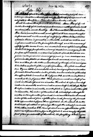
To all to whom these presents shall come, Joseph Fox of Lowell in the county of Middlesex and commonwealth of Massachusetts mechanician, sends Greeting. Be it known that the said Joseph Fox, have invented, made and applied to use a new & useful improvement in the mode of supplying steam boilers, or boilers wherein steam is generated, with water, which invention and improvement, and the principles thereof, and the manner of applying the same to use, are described and explained as follows, that is to say, perspective views of machines used by me for the purpose aforesaid, and drawings of parts of such machines are given in the plates or drawings of pages of this specification are given in the plates or drawings hereto annexed, numbered one two and three for the better understanding thereof, which drawings are to be taken as parts of this my specification. A in plate numbered one Figures 1832, is a moveable wheel, having a fixed axis, whose journals turn & revolve in two plates, one on each side of the wheel, the upper plate is marked B in figures 1832, and the under plate is marked C, in figures 1832. These plates are each one half of an inch in thickness and are circular. The wheel A is four & one half inches in diameter and one inch and one half in thickness. The plate B is five inches in diameter, and the plate C, is four inches & three eighths in diameter. The axis of the wheel A, which passes through its centre, is three fourths of an inch in diameter & extends on each side of the wheel five eighths of an inch, forming the journals D1B, represented in figure three of plate 1. In the wheel A are two sectional apertures or openings through the wheel from inside to the other, marked E,F; these apertures are on opposite sides of the axis as represented in figure 2 of plate 1, and occupy the quarter part of two quadrants of the wheel; the periphery O, O being one fourth
Drawing
Page 3.
573 6964X Mar 14, 1832
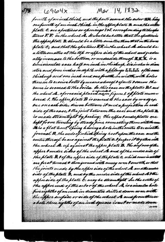
fourth of an inch thick, and the parts around the axis D, being one fourth of an inch thick, in the upper plate B, and the under plate C, are apertures or openings I, I, corresponding to the apertures E, E, in the wheel A. It would be better that the apertures in the upper plate B, should be a little smaller than that in the lower plate C; and that the apertures E, E, in the wheel A should be a little smaller at the top or upper side of the wheel and gradually increase to the bottom, or underside thereof. B, K, K, is a univiscous case half an inch in thickness, six inches in diameter and four inches in depth with a flange I, I, I, I, of the same thickness and one inch and one fourth in width, with holes therein to receive bolts by means whereof it is to be secured the same is secured to the boiler. In this case are the plates B, C, and the wheel A, aforesaid placed as in figure 1. of plate numbered 1. The upper plate B is secured to the case by wedges, one on each side, driven between it and a projection on each side of the case, & the joint between the case and the plate B, is made steamtight by packing; The upper & under plates are kept from turning by steady pins, connecting them with the case. D is a flat bent spring having a hole in the centre to receive the journal B, the ends of which spring rest upon the case and the centre thereof bears against the plate C, & keeps it together with the wheel A up against the upper plate B. The surfaces of the upper & under sides of the wheel A and of the under side of the plate B, & of the upper side of the plate C, which come in contact are first turned & then ground with emery wool & smooth, so that the joints made by the upper side of the wheel A and the under side of the plate B, and by the under side of the wheel A & the upper side of the plate C, may be steamtight. In the centre of the upper end of the axis of the wheel A, is a circular hole five eighths of an inch in diameter drilled down even with the upper surface or side of the wheel A and from thence a hole three eighths of an inch space is cut or made down
Page 4.
even with the under side or surface of the wheel A. In a projection on the flange T, is drilled a hole three-fourths of an inch in diameter, corresponding with the hole O in the upper plate B and leaving its axis to coincide with the center of the hole O in said plate B, but the hole in the other projection of the said is fitted therein in a shaft N which has a collar upon it resting upon the flange so as to prevent the shaft from going further than within one-fourth of an inch of the bottom of the square hole in the axis of the wheel A aforesaid. That part of the shaft N which goes into the hole aforesaid in the axis of the wheel A and one-fourth of an inch more is made square and of dimensions corresponding nearly with that part of the hole which is square, but a very little wider so that a slight inclination of the shaft may not affect the position of the wheel A; that part of the shaft underneath the collar, which is in the hole made through the projection in the flange is round and made to correspond with that hole. Q Q, are two holes made through the top of the case and through the upper plate B one-fourth of an inch apart, and opposite to the aperture I in said plate B, occupying a less space than the said aperture, so that, when either of the apertures P P, in the wheel A are by its revolution brought immediately under the said holes, & they are, as nearly as may be, in the center thereof, the outer edge of each of the said holes may then be three-eighths of an inch from the edge of the aperture, in order to prevent the steam from passing from the boiler and rushing up those holes. On the top of the case is a cap R secured thereto by screws, in which case are two holes a little larger than those last described so as to admit the pipes S T, the valves of which are of the same diameter with & correspond to the holes Q Q in plate B, which pipes are tightly fitted into the said cap. The pipes S T each communicate with separate fountains of water a few feet above the boiler, the level of the fountain with which the pipe S communicates being a little below the level of the fountain with which the pipe T communicates; so as to create a greater pressure of water in the pipe T in order that in case the steam misbehaves should enter & rise of the water in the pipe S & hold it in suspension, the water in the pipe T when the pressure
Page 5.
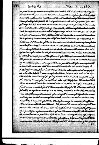
is greater may descend and fill the cavities D D, in the wheel A, as by its revolution they are made to pass underneath successively. A hole of sufficient length and breadth must be cut in the head of the boiler to admit those parts of the plates B, C, & of the wheel A, which project beyond the flange I, I, I, I, and so that when the case is fixed upon the boiler and secured thereto with packing, the middle of the rim of the wheel A, which is to be so placed as to move horizontally, shall be on the same level at which it is desired to keep the water in the boiler, and that there shall be a space of about one fourth of an inch above the upper plate B, & between it & the edge of the hole made in the boiler and a space of about one half an inch underneath the under plate C, and between it and the edge of the hole made in the boiler to admit the steam into the spaces & apertures in the plates & wheel from the boiler & to allow the water to escape from the spaces & apertures aforesaid into the boiler. The plate C, is made a little smaller than the wheel A, so that the pressure of the steam upon it may not be so great as the pressure upon the wheel A, in order, that in case the water in the cavities D D, in piping from the pipes into the boiler should expand, it may drop down the plate C and escape between it and the wheel A into the boiler, instead of piping down the wheel A and allowing the steam to escape from the boiler up the pipes. The wheel A is to be made to revolve in such direction that the apertures D D, in first come under pipe S & then under the pipe T. The case, wheels & plates, may be made of cast iron, or other suitable material. The shaft may be made of wrought iron excepting the lower end, which goes into the axel of the wheel, which as well as said axel or ought to be made of steel. The pipes may be made of copper or other like suitable material. The power to move the shaft N and cause the wheel A to revolve is applied to the said shaft by means of a pulley or a pinion wheel upon the said shaft. As the wheel A revolves the apertures D D, therein are brought successively over or so as to correspond with the apertures I I, I, in the plates B, C, and under the holes below the pipes S & T. When either of the apertures
Page 6.
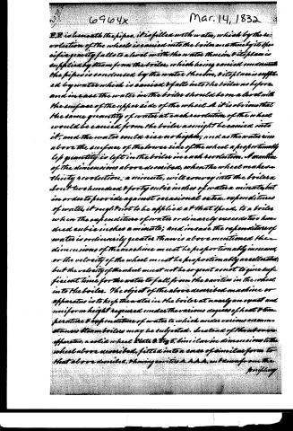
E.P. is beneath the pipes, it is filled with water, which by the revolution of the wheel is carried into the boiler and there by its specific gravity falls to a level with the water therein, & its place is supplied by steam from the boiler, which being carried underneath the pipes is condensed by the water therein, & its place is supplied by water which is carried & falls into the boiler as before, and in case the water in the boiler should be on a level with the surface of the upper side of the wheel & it is obvious that the same quantity of water at each revolution of the wheel would be carried from the boiler as might be carried into it, and the water could rise no higher; and as the water rises above the surface of the lower side of the wheel a proportionally less quantity is left in the boiler in each revolution. A machine of the dimensions above described, when the wheel makes thirty revolutions a minute, will convey into the boiler about two hundred & forty cubic inches of water a minute, but in order to provide against occasional extra expenditures of water, it ought not to be applied at that speed, to a boiler when the expenditure of water ordinarily exceeds two hundred cubic inches a minute; and in case the expenditure of water is ordinarily greater than is above mentioned, then dimensions of the machine must be proportionally increased, or the velocity of the wheel must be proportionally accelerated; but the velocity of the wheel must not be so great as not to give sufficient time for the water to fall from the cavities in the wheel into the boiler. The object of the above described machine or apparatus is to keep the water in the boiler at nearly an equal and uniform height required under the various degrees of heat & temperature & expenditure of water to which under various circumstances steam boilers may be subjected. Instead of the above apparatus, a solid wheel Plate B Fig 5, similar in dimensions to the wheel above described, fitted into a case of similar form to that above described, having cavities A A A, cut now from the
Page 7.
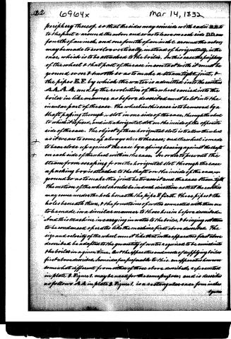
periphery thereof, so that the sides may coincide with radii BB to the point e around the axis, and so as to leave on each side DD one fourth of an inch, and one fourth of an inch c. around the axis, may be made to revolve vertically, instead of horizontally, in the case, which is to be attached to the boiler. In this case the periphery of the wheel & that part of the case in contact with it must be ground very smooth so as to make a steam-tight joint, & the pipes E.E. by which the water is admitted into the cisterns A.A.A.A. and by the revolution of the wheel carried into the boiler in like manner as before described must be let into the circular part of the case. The wheel in this case is to be moved by a shaft passing through a slot in one side of the case, through the wheel to which it is fixed, and into a horizontal slot on the inside of the opposite side of the case. The object of these horizontal slots is to allow the wheel as it wears to come up always close to the case; and the wheel is made to bear close up against the case by a spring bearing against the shaft on each side of the wheel within the case. In order to prevent the steam from escaping from the horizontal slot through the case a packing box is attached to the shaft on the inside of the case, & ground so as to make the joint between it and the case steam-tight. The motion of the wheel should be in such direction as that the cisterns may come under the hole beneath the pipe E first. These pipes & the holes beneath them, & the fountains of water connected with them are to be made in a similar manner to those herein before described. And this machine in carrying in water to the boiler, & bringing out steam to be condensed operates like the machine first above described. The size and velocity of the wheel must like that in the apparatus first above described be adapted to the quantity of water required to be carried into the boiler in a given time. But the apparatus and mode of supplying boilers first above described, I consider far preferable to this. an apparatus however somewhat different from either of those above described, & represented in plate 3. Figure 1. may be used for the same purpose, and is described as follows: A.A. in plate 3. Figure 1. is a rectangular case four inches
Page 8.
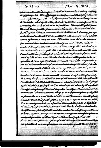
square on the outside, half an inch thick & seven inches long including the filange BB. These filanges are half an inch thick & project an inch and one fourth beyond the case, by one of which the case is confined to the boiler; and by the other of which the plate C, one half inch thick, covering that end of the case, is fastened. Through this plate passes the rod D one fourth of an inch in diameter around which is a packing box. This rod is connected with the slide E, having prongs which act in the slot D, so as that the slide may be moved back ward & forward with the rod. This slide moves backward and forward three inches and is thereby moved into the boiler two inches & three fourths & thence back alternately, it is six inches & three fourths in length, three inches in breadth, and two inches & one fourth in thickness. One inch & three fourths from the end of the slide next to the boiler, is a rectangular hole or aperture & through the slide one inch in width lengthwise of the slide & two & an half inches widthwise of the slide.) The slide in moving out of the boiler is brought back until the opposite end comes to the inner side of the plate C & the end next to the boiler is drawn in drawn into the case one fourth of an inch. H is one half an inch thick and of the same width & length with the slide E, & fitted into the case under said slide and kept up against it by a spring I, which also keeps the slide tight against the upper surface of the rectangular cavity in the case in which it moves. Two inches & an half of the upper surface of the plate H from the end next to the plate C, is cut down one fourth of an inch so that this part of the surface may not touch the slide. J is a rectangular hole or aperture through the plate H Fig 3 P.L.D. three inches from the end next to the boiler, half an inch wide lengthwise of that plate and two inches & an half long widthwise of the same plate; through which the steam may pass through a space under the plate so as to act against the slide & push it up with more force than the plate is pressed up with thereby to allow the steam in the aperture & in case of expansion in passing into the boiler to escape.
Page 9.
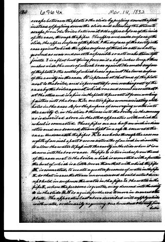
escape between the plate & the slide by pressing down the plate instead of pressing down the slide and allowing the steam to escape from the boiler between it, & the upper surface of the inside of the case, through the pipes. The upper and under surface of the slide, the upper surface of the plate, & the surface of the cavity in the case against which the upper surface of the slide acts are all ground as even and smooth as possible so as to make steam tight joints. I is a flat bent spring four and a half inches long, & three inches wide the ends of which bear against the under surface of the plate & the center of which bears against the lower surface of the cavity in the case. It is placed at that end of the plate next to the boiler, and is prevented from working out of the case by the boiler against, which one end comes in contact, & at the other end is a pin in the plate to prevent it from working farther into the box. K I, are two pipes communicating with holes in the case A for the purpose of conveying water into the cavity C in the slide & thence into the boiler, in the same way as is described above in the other apparatus with which the wheel is connected. These pipes are one half an inch in diameter and are secured steam tight in a cap D screwed to the case. Underneath the pipes K I are holes through the case one eighth of an inch apart & seven sixteenths of an inch in diameter, to allow the water to pass into the cavity in the slide when it is drawn into the box or case. The pipe I is two inches from the end of the case next to the boiler, which is connected with a foot valve the level of which is a little lower than that with which the pipe K is connected, to create a greater pressure of water in the pipe K, so that in case the steam uncondensed should enter & drive up & hold in suspense the water in the pipe I, the water in the pipe K, where the pressure is greater, may descend into the cavity C in the slide. E N is a guide for the rod to move in secured to the plate. The apparatus last above described will supply a slide with water, ordinarily requiring one hundred twenty five cubic
Page 10.
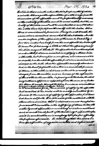
but is in less a minute, when the slide performs thirty strokes a minute. When a greater expenditure of water is required, the dimensions of the apparatus must be proportionally increased, or the velocity of the slide must be accelerated; but the velocity of the slide must not be accelerated so as not to allow the water time to fall from the cavity into the boiler. When there is considerable pressure it may be well to make the cases above described somewhat thicker & stouter. And the under surface of the upper side of the case A. Plate 3. Fig. 1. for two inches & an half from the end opposite the boiler may to be cut or filed away a little so that the upper surface of the slide may not touch it. The apparatus last mentioned operates as well as that first above described in supplying a steam boiler with water, but it occupies more space, and is deemed not to be so durable, & on the whole the apparatus first above described is considered as the best. And the apparatus secondly above described is the least preferable where there is a considerable pressure of steam, as the water in that case will not be so readily discharged from the cavities, and as, in case of the expansion of the water in the cavities, in passing into the boiler, the wheel may be thrown off from or separated from the case so as to allow the steam to escape through the pipes, & under no circumstances by any means as the apparatus firstly or lastly for described.
So it considered so good, the manner of applying the apparatus last described to the boiler will be readily understood by reference to the manner of applying the apparatus first described herein set forth. It is to be made of like materials with the others above described. What is claimed as a new & useful improvement & invention, is the supplying of steam boilers with water by such apparatus or machinery as is above mentioned and so much & such parts of the machinery & apparatus of as said in combination as is necessary & proper for effecting the purposes aforesaid. In testifying that the above is a true specification of my said invention and improvement above
Page 11.
Mar. 14, 1832
above described. I have hereunto set my hand and seal this tenth day of February in the year of our Lord eighteen hundred and thirty-two.
Signed, sealed & executed in presence of us
Lysd. B. R. Rand
Mfco. Augustus H. Fiske
(4108 mms)
Published accounts: journal notice
Notice in the monthly list of patents, with remarks
Journal of the Franklin Institute, new ser., vol. 10 (1832), p. 160 · View the page
14. For an improvement in the Manner of supplying Steam Boilers; Jesse Fox, Lowell, Middlesex county, Massachusetts, March 14.
Remarks. Those who are well acquainted with the different modes which have been adopted for supplying boilers with water, know that it is sometimes done by causing a cylinder, or a conical plug, to revolve in a suitable case, like the key of a cock in its socket, and having at one point, a cavity within it, which as it turns, is filled with water from a reservoir above it, and in its revolution delivers it therefrom into the boiler. The plan before us is of this character, but in the structure and arrangement of its parts appears to be new, and well conceived; without the aid of a plate, however, we can attempt no more than a very general description of it. The revolving piece which has the cavities in it for the reception and supply of water, is a cylinder of iron four inches and a half in diameter, and one and a half in thickness; this cylinder revolves on a suitable axis, being enclosed for more than half its circumference in a casing, which is furnished with a flanch, by which the apparatus is attached to a boiler. A hole is made in the boiler to admit a projecting part of the revolving supply wheel, which is nearly equal to one-half of it. This wheel is perforated on opposite sides, so as to remove nearly one half of its substance. Imagine it to be divided into four parts, or quadrants, the part removed consists of two opposite quadrants, leaving a rim, however, of one-fourth of an inch in thickness at the outside, and an equal portion round the gudgeon at the centre. These cavities, as the wheel revolves, are alternately exposed to the pressure of water in a reservoir from which they are filled, and to the inside of the boiler, into which the water falls from them, both sides of the wheel being equally acted upon by the steam. The perforation of the boiler is at the point intended for the water line, in order that the tendency of the wheel may be to carry back as much as it supplies when the boiler is sufficiently full. The claim is to the apparatus as described. A principal objection to revolving wheels of this description is their gradual wear, which, although they may operate satisfactorily at first, soon unfits them for the duty they are to perform. Should this objection be removed, the principle is undoubtedly a good one.
About this record
- Patentee
- DATAMP
- Date
- the Name and Date index of patents, DATAMP, USPTO records
- Invention
- DATAMP
- Listed in
- the Name and Date index of patents, DATAMP, USPTO records, Jim Shaw's X-patent list, the Journal of the Franklin Institute, Burke's List of Patents (1847)
- Burke's 1847 Patent Office list gives the same patent.