

Drawings and documents
National Archives restored drawings: drawing
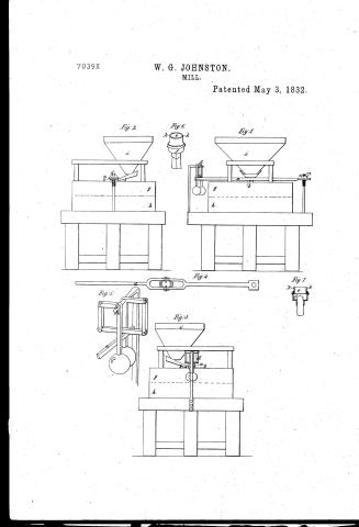
William G. Johnston's Patent Drawing for an Improvement in Mills

National Archives, Restored Patent Drawings (Record Group 241) · Full-size scan at the National Archives · Catalog record
Show the text on the drawing Hide (159 words)
Words on the drawing as machine-read by the National Archives; not checked. Useful mainly for searching.
(83) MILLS. / CLASSIFICATION / Grinding Mills. / Disk Action: Horizontal. / 7039 X / DIV ISION. / William I Johnston / # 7039x X / Tigh / Improvement in Mills. / Vol. Ir pg 201. / Patented May 3. 1832, / Perspective view of / compouned lever d / 164/ / Topvicw of horizon tal leven a and boxes or collars exf. / Perspective Vi view of the / Section / collars c & t. xt. / Jig.5. / K. / Big / Sig.1 / Fig.2 / the / Sig.3. / C= / Sideview. / Trant view / Sideview / mobe of hucara drumeshing the weighty / manir bya self regulating company power to / Preferences a horizontal Lever bib bearing points c sereio to regula to the leaser d compouned lever e the movemble collar / fthe fixed collangthe runner. h. bedstone i hopper. KK notchesfor for the bearing points to rest upon. see Jig7 / Patent affice Decem ber by / Made under childination of the Commissioner of / in conformity with act of s March ixer / WLSUMSOMI / cholic Leit / Commissioner of Patents
USPTO scan
The patent as scanned by the USPTO
-
 Page 1
-
 Page 2
-
 Page 3
-
 Page 4
-
 Page 5
-
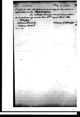 Page 6


U.S. Patent and Trademark Office · Google Patents
Show the transcription Hide (1,314 words)
Machine transcription (LightOnOCR) of the pages as scanned by the USPTO, most of them the handwritten copies made when the records were restored after the 1836 fire. Not checked; it can misread handwriting, so compare it with the scan.
Page 1.
7039X
W. G. JOHNSTON.
MILL.
Patented May 3, 1832.
Fig. 2
Fig. 6
Fig. 1
Fig. 4
Fig. 5
Fig. 3
Fig. 7
Page 2.
7039x
May 3, 1832
William G. Johnston, Philadelphia Pa.
Letters Patent.
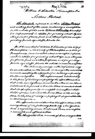
The Schedule referred to in these Letters Patent, and making part of the same, containing a description in the words of the said William Johnston himself of his improvement in mills for grinding wheat, rye and other grain for flour, feed and other purposes, and for grinding paints, dye stuffs, plaster &c.
Be it known that I William G. Johnston of the city of Philadelphia, in the county of Philadelphia and state of Pennsylvania, have invented a new and useful improvement in mills for grinding wheat, rye, and other grain for flour, feed and other purposes; and for grinding paints, dye stuffs, plaster &c. which is described as follows:
The mill and gearings, with its fixtures may be constructed in the usual, or in any other convenient manner; excepting the apparatus for holding or pressing the stones together. The improvement relates solely to the plan of holding or pressing the upper stone (when that is the moving stone) down on the other or on the substance to be ground, when the stone is made so small that its specific gravity, or weight, is insufficient for that purpose; and when the lower stone is the moving stone, to the plan of raising, or pressing it up against the other or stationary one.
The apparatus consists (when the upper stone is the moving stone) of the following parts, viz. a horizontal lever, a regulating screw, compound levers, and weights; a movable and affixed collar.
The horizontal lever is made of iron or angle iron.
Page 3.
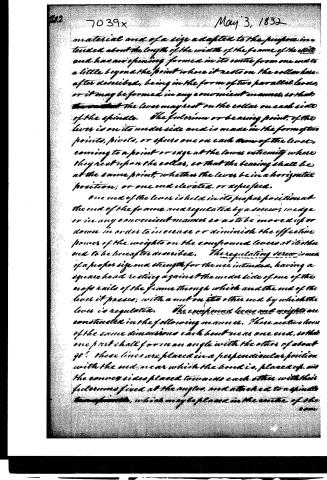
material and of a size adapted to the purpose intended about the length of the width of the frame of the mill and has an opening formed in its centre from one end to a little beyond the point where it rests on the collar hereafter described, being in the form of two parallel levers, or it may be formed in any convenient manner, so that the lever may rest on the collar on each side of the spindle. The fulcrum or bearing point of the lever is on its under side and is made in the form of two points, pivots, or eyes one on each arm of the lever, coming to a point or edge at the lower extremity where they rest upon the collar, so that the bearing shall be at the same point, whether the lever be in a horizontal position; or one end elevated, or depressed.
One end of the lever is held in its proper position at the end of the frame and regulated by a screw, wedge or in any convenient manner so as to be moved up or down in order to increase or diminish the effective power of the weights on the compound levers at its other end to be hereafter described. The regulating screw is made of a proper size and strength for the use intended, having a square head resting against the under side of one of the cross rails of the frame through which and the end of the lever it passes; with a nut on its other end by which the lever is regulated. The compound levers and weights are constructed in the following manner. There are two levers of the same dimensions each bent near one end, so that one part shall form an angle with the other of about 90°. These lines are placed in a perpendicular position with the end near which the bend is, placed up, and the convex sides placed towards each other with their fulcrums fixed at the angles, and attached to a spindle, which may be placed in the centre of the cam.
Page 4.
compound levers; or to a cross bar allashed to said spindle, or to some other permanent object, in such manner that the ends of the levers may move towards or from each other. ... There are three short bars attached at the ends by levers like hinges so that they will bend at the joints; one end of this connection of bars is attached to the upper end of one of the bent levers, and the other end to the upper end of the other bent lever, in such manner that the middle bar of the three above mentioned is in a horizontal position, and placed across the end of the above described horizontal lever. A ball or weight is attached to the lower end of each bent lever.
The moveable and fixed collars of metallic cylindrical collar is fixed permanently to the spindle. Immediately above this and resting upon it is a moveable collar so fixed, that the spindle may turn freely within it having two small indentations on its upper surface in which rest the points, pivots, or spurs on the underside of the lever first described.
Operation
The mill being put in motion in the usual manner by water, steam, or any convenient power, the operation of the before described apparatus for holding the stones together will be as follows.
When the upper stone is raised or lifted up from the other by any cause whatever, the balls or weights are forced apart and raised, increasing their effective weight or power, and when the upper stone settles towards the other, the balls or weights settle and approach each other by which their effective weight or power is diminished; the apparatus resembling in construction and operation the governor of a steam engine.
Page 5.
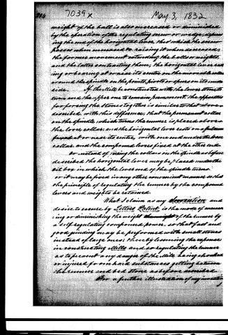
weight of the ball is also increased or diminished by the operation of the regulating screw or wedge, depending the use of the horizontal lever, that which the screw possesses when increased to raising it when decreased, the former movement extending the balls or weights, and the latter contracting them; the horizontal lever resting or bearing at or near its centre on the moveable collar around the spindle on the points, pivots or spurs on its inner side. If the mills be constructed with the lower stones to turn and the upper one to remain permanent, the apparatus for forcing the stones together is similar to that above described, with this difference; that the permanent collar on the spindle, which turns the runner is placed above the loose collar, and the horizontal lever rests on a fulcrum fixed at or near its centre, with one end under the base collar, and the compound lever fixed at the other end.
Or instead of using the collars on the spindle as before described the horizontal lever may be placed under the oil box in which the lever end of the spindle turns.
Or it may be fixed in any other convenient manner so that the principle of regulating the runner by the compound levers and weights to be retained.
What I claim as my invention and desire to secure by Letters Patent is the mode of increasing or diminishing the weight of the runner by a self-regulating compound power, so that fast and good grinding may be performed with small stones instead of large ones; thereby lessening the expense in constructing mills and so regulating the runner as to prevent any danger of the mill being shaken or injured from hard substances getting between the runner and bed stone as before described.
For a further illustration of my invention
Page 6.
May 3, 1832
I refer to the model and drawing of the same as deposited in the Patent Office.
In witness whereof I have hereunto subscribed my name this 28th day of April 1832.
Witnesses
William P. Colby
William Webber
William G. Johnston
1210 n8
Published accounts: journal notice
Notice in the monthly list of patents, with remarks
Journal of the Franklin Institute, new ser., vol. 10 (1832), p. 320 · View the page
1. For a Mill for Grinding Grain, Paints, &c.; William G. Johnson, city of Philadelphia, May 3.
Remarks. This mill is to be constructed in the usual manner, excepting the apparatus for pressing the stones together, which apparatus, we are informed by the patentee, consists of a horizontal lever, a regulating screw, compound levers and weights, and a moveable and fixed collar. In form and action this apparatus bears a near resemblance to the governor of a wind mill, or steam engine, but it is not made to revolve, being acted upon in another way. When the stone is raised, it presses against a lever, connected with the governor, and this throws out the two balls, or weights, causing them to act with greater force, upon the stone, and thus prevent its further rise. The effective pressure upon the stone is in this way increased, or diminished, as it rises from, or approaches towards, the bed stone. It is this particular arrangement which forms the subject of the claim.
About this record
- Patentee
- DATAMP
- Date
- the Name and Date index of patents, DATAMP, USPTO records
- Invention
- DATAMP
- Listed in
- the Name and Date index of patents, DATAMP, USPTO records, Jim Shaw's X-patent list, the Journal of the Franklin Institute, Burke's List of Patents (1847)
- The Franklin Institute's journal spells the name differently.
- Burke's 1847 Patent Office list gives the same patent.