

Drawings and documents
USPTO scan
The patent as scanned by the USPTO
-
 Page 1
-
 Page 2
-
 Page 3


U.S. Patent and Trademark Office · Google Patents
Show the transcription Hide (785 words)
Machine transcription (LightOnOCR) of the pages as scanned by the USPTO, most of them the handwritten copies made when the records were restored after the 1836 fire. Not checked; it can misread handwriting, so compare it with the scan.
Page 1.
7041X
J. L. Colman,
Wind Wheel,
Patented May 4, 1832
Fig. 1
Fig. 2
Page 2.
7041X
May 4, 1852
Jeremiah L. Colman
Letters Patent
The declaration refers to in the Letters Patent and making part of the same containing a description in the case of the said Jeremiah L. Colman himself of his improvement called the self-regulating Horizontal Wind Mill.
Be it known that I, Jeremiah L. Colman of Vincennes of the County of Perry and State of Indiana have invented a new and useful improvement in the application of wind to machinery and that the following is a full and exact description of the construction and operation of said machine as invented by me Jeremiah Colman of Vincennes a J. L. Colman's self-regulating horizontal wind mill, for working any kind of machinery, which is propelled by applying weight to sails.
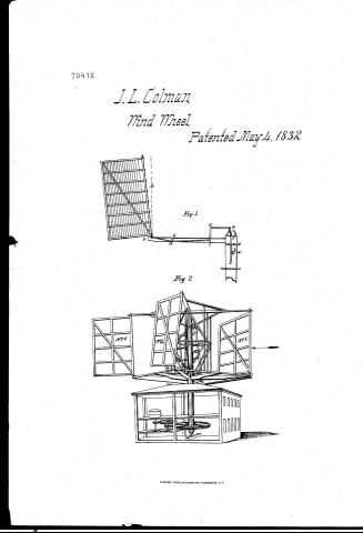
Figure 1 represents one of the wings or sails standing inclined to the left or backwards from dotted line A, which throws a weight of the wing to the left. The inclination may be more or less than represented by the wing and dotted line agreeable to the natural weight of the wing. But give it such inclination back from the way which the wind mill is calculated to run as will give sufficient weight to drive say one light ton of millstones, if more power is desired and the same sufficiently strong, add more weight to the wings or give the wings more inclination which may be effected by hand, stopping the mill and moving a piece of timber on which the wings turn, or at D, where said timber moves on a smooth surface turning on a pivot on the axis at C, or the wings may be inclined more or less without stopping the mill by the following described machinery, viz: By a piece of oak iron with teeth as represented at D, which moves up and down in a groove in the wind shaft and passes under a cast iron collar on the wind shaft as at E, with moving joints at E and E', where it is attached to a triangular frame of wood or iron with a stationary pivot at H, a piece of timber moving from I, where there is another moving joint to K, where it joins on a triangular as the one above described, by a man standing on a wheel or platform on wind shaft at L, and turning a handle.
Jeremiah L. Colman
Page 3.
small pinion wheel with a crank at M. The cast iron with teeth represented at D is much of a round wheel whose lower portion of the curve at B, by the above described machinery, is attached thereto by which more or less power may be given. Figure 2 is a view of a mill in operation on a large breeze of wind. Wing N° 1 receiving the wind on its back side as it comes from the west. Wing N° 2 receiving the wind on its back the same as above. Wing N° 3 coming with its thin side to the wind. Wing N° 4 receiving the wind as it comes from the east facing in front of wing N° 2 and back of wing N° 3 which wing stands as a ventilator and has its thin side in front of wing N° 4. Each wing performing one revolution on its pivot to one of main wind wheel if the wind be sufficient. The above described mill is safe with almost any sized wings, as each wing during a storm stands with its thin edge to the wind, the wind having little more power if any than the given weight of the wings on the wind. In stopping the mill, friction levers may be lightly drawn around each of the wheels by a cord or rope which will be sufficient to overbalance the weight of the wings above and the mill stops. All the gearing within the wind wheel at N in Figure 2 may be dispensed with on a small scale, leaving the center post sufficiently large. The running gears may be as in any other mill geared from a vertical shaft to suit such machinery as is calculated to be done. The machinery ought to have its proper space when the wings are moving, say 5 miles an hour—a little more or a little less will do. The wings may be covered with light boards or canvass. Known as March 27, 1852.
Jasemiah S. Colman
To:
W. Hopkins
G. W. Johnson
G. W. Rathbone
About this record
- Patentee
- DATAMP
- Date
- the Name and Date index of patents, DATAMP, USPTO records
- Invention
- DATAMP
- Listed in
- the Name and Date index of patents, DATAMP, USPTO records, Jim Shaw's X-patent list, Burke's List of Patents (1847)
- Burke's 1847 Patent Office list gives the same patent.