

Drawings and documents
USPTO scan
The patent as scanned by the USPTO
-
 Page 1
-
 Page 2
-
 Page 3
-
 Page 4
-
 Page 5


U.S. Patent and Trademark Office · Google Patents
Show the transcription Hide (1,025 words)
Machine transcription (LightOnOCR) of the pages as scanned by the USPTO, most of them the handwritten copies made when the records were restored after the 1836 fire. Not checked; it can misread handwriting, so compare it with the scan.
Page 2.
United States Patent
Patent No.: X7194
Cotton Foss
Letters Patent.
The Schedule referred to in these Letters Patent and making part of the same, containing a description in the words of the said Cotton Foss himself of his improvement in the inclined water wheel.
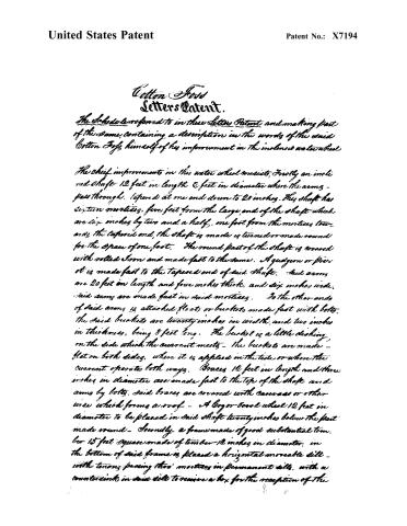
The chief improvements in this water wheel consists, firstly an inclined shaft 12 feet in length & feet in diameter where the arms pass through, tapered at one end down to 20 inches. This shaft has sixteen mortises, five feet from the large end of the shaft which are six inches by two and a half. One foot from the mortises towards the tapered end, the shaft is made is turned or made round for the space of one foot. The round part of the shaft is covered with rolled iron and made fast to the same. A quaggon or pivot is made fast to the tapered end of said shaft. Said arms are 20 feet in length and four inches thick, and six inches wide. Said arms are made fast in said mortises. To the other ends of said arms is attached floats or buckets, made fast with bolts. The said buckets are twenty inches in width, and two inches in thickness, being 8 feet long. The bucket is a little dishing on the side which the current meets — the buckets are made flat on both sides, where it is applied in the tide or where the current operates both ways. Braces 12 feet in length and three inches in diameter are made fast to the top of the shaft and arms by bolts. Said braces are covered with canvas or other wire which forms a roof — A log or barrel wheel 12 feet in diameter to be placed in said shaft twenty inches below the part made round — Secondly, a frame made of good substantial timber 15 feet square made of timber 12 inches in diameter. In the bottom of said frame is placed a horizontal moveable sill — with tenons passing thro’ mortises in permanent sills, with a counter sink in said sills to receive a box for the reception of the
Page 3.
United States Patent
Patent No.: X7194
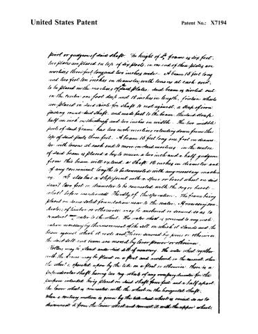
pivot or guides of said shaft. The height of said frame is six feet. Two plates are placed on top of six posts, in one end of these plates are mortises three feet long and two inches wide — a beam 15 feet long and two feet ten inches in diameter, with tenons at each end, to be placed in the mortises of said plates. Said beam is circled out in the centre one foot deep and 18 inches in length. Friction wheels are placed in said circle for shaft to rest against, a strap of iron passing round said shaft, and made fast to the beam. The said strap half an inch in thickness and two inches in width — The two middle posts of said frame has two inch mortises extending down from the top of said posts three feet. A beam 15 feet long one foot in diameter with tenons at each end to move in said mortises — in the centre of said beam is placed a box to receive a two inch and a half guage from this beam will extend a shaft 12 inches in diameter and of any convenient length to be connected with any necessary machinery. It also has a step joint with a spur or bevel wheel on said shaft two feet in diameter to be connected with the cog or bevel wheel before mentioned. Thirdly of the operation: The frame being placed on some solid foundation near to the water. If necessary conductors of timber or otherwise may be anchored or secured so as to conduct the water to the wheel. The water wheel is grounded to any inclination necessary by the movement of the sill on which it stands and the beam against which it rests and there secured by pins or otherwise. The said sill and beam are moved by lever power or otherwise. Holes may be placed under said sill if necessary. The water wheel together with the frame may be placed on a float and anchored in the current, when the wheel is operated upon by the tide on a float or otherwise. There is a perpendicular shaft having two cog wheels of any overpassing diameter for the purpose intended, being placed on said shaft four feet and a half apart. The lower wheel is connected with the wheel on the horizontal shaft. When a contrary motion is given by the tide said wheel is raised so as to disengage it from the lower wheel and connect it with the upper wheel.
Page 4.
United States Patent
Patent No.: X7194
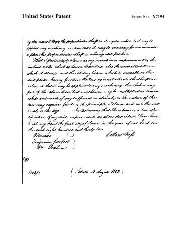
by this means it keeps the perpendicular shaft on its regular motion. To it may be applied any machinery. In some cases it may be necessary for convenience to place this perpendicular shaft in a horizontal position.
What I particularly claim as my invention or improvement is the inclined water wheel as herein described, also the movable sill on which it stands and the sliding beam which is movable on the said plates, having friction rollers against which the shaft revolves, so that it may be applied to any machinery. The whole or any part of the above described machine, may be multiplied or diminished and made of any sufficient materials, as the nature of the case may require, for it is the principle I claim and not the materials or the size.
In testimony that the above is a true specification of my said improvement as above described, I have here to set my hand the first day of June in the year of our Lord one thousand eight hundred and thirty two.
Witnesses
Benjamin Crofoot
Wm. Graham
Cotton Shop
140
(1027)
(Patented 11 August 1832)
Page 5.
United States Patent
Patent No.: X7194
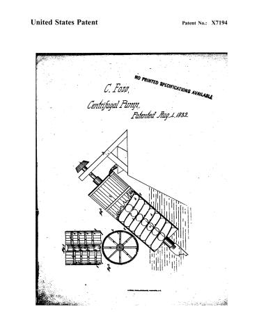
NO PRINTED SPECIFICATIONS AVAILABLE
C. Foss,
Centrifugal Pump,
Patented Aug. 1, 1832.

Published accounts: journal notice
Notice in the monthly list of patents, with remarks
Journal of the Franklin Institute, new ser., vol. 11 (1833), p. 159 · View the page
4. For an Inclined Water Wheel; Cotton Foss, Perry, Geauga county, Ohio, August 4.
Remarks. The water wheel described in the specification of this patent, is intended for a tide and current wheel. It consists of a shaft inclined from the perpendicular in any required degree, and capable of having this inclination raised by sliding blocks, or beams, in which its gudgeons run. The floats, or buckets, are formed like oars, and are attached to arms forming radii with the shaft. The claim made is to "the inclined water wheel as herein described; also the moveable sill on which it stands, and the sliding beam which is moveable in the said plates." The wheel is to be fixed in proper frame work by the water side, or it may be moored in the water, or otherwise placed, so as to answer the intended purpose. In what it is superior to numerous other tide and current wheels, we are not informed, nor are we able to discover; and, as at present impressed, should prefer the ordinary vertical wheel, made in the manner of the common undershot.
About this record
- Patentee
- DATAMP
- Date
- the Name and Date index of patents, DATAMP, USPTO records
- Invention
- DATAMP
- Listed in
- the Name and Date index of patents, DATAMP, USPTO records, Jim Shaw's X-patent list, the Journal of the Franklin Institute, Burke's List of Patents (1847)
- The X number was worked out from the patent’s place in the date sequence.
- Burke's 1847 Patent Office list gives the same patent.