

Drawings and documents
National Archives restored drawings: drawing
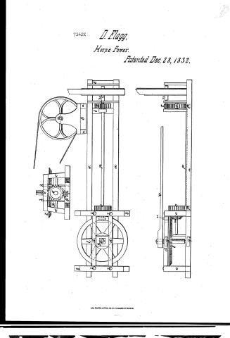
Daniel Flagg's Patent Drawing for a Machine for Portable Horse Power

National Archives, Restored Patent Drawings (Record Group 241) · Full-size scan at the National Archives · Catalog record
Show the text on the drawing Hide (112 words)
Words on the drawing as machine-read by the National Archives; not checked. Useful mainly for searching.
[159] Horse Powers. / MECHANICAL POWERS / Honor-power / 83- / David Hago / Portable Horse Power / Voe 14 pg. 477. / CLASSIFICATION / Patented Dec 28. 1832. / 7342-X / DIV ISION / B. / Preferences a.a sills b. bb.b crofs sills e.e.e.e. posts. d d cross pieces. 33 plates. hh hhbotto i head block. K Kgirts l Mainwheel and shaft. / m pinion n friction wheel o cogwhel p.p.pinionsand line shaft .5' cogwheel t pinion on the band what shaft u v. lever. / made under the direction of the Commissioner / Patent Office December Patents / in conformity with het of 3d march 1837. / Md Sumoch / Comminioner of Patents.
USPTO scan
The patent as scanned by the USPTO
-
 Page 1
-
 Page 2
-
 Page 3


U.S. Patent and Trademark Office · Google Patents
Show the transcription Hide (801 words)
Machine transcription (LightOnOCR) of the pages as scanned by the USPTO, most of them the handwritten copies made when the records were restored after the 1836 fire. Not checked; it can misread handwriting, so compare it with the scan.
Page 1.
7342X
D. Flagg,
Horse Power.
Patented Dec. 28, 1832.

A.M. PHOTO-LITHO. CO. N.Y. (OSBORNE'S PROCESS)
Page 2.
Dec. 28, 1832
7342x David Hagg jun.
Letters Patent.
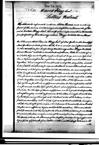
The schedule referred to in these Letters Patent, and making part of the same, containing a description in the words of the said David Hagg jun. himself of his improvement in the machine for propelling machinery called "Haggs Portable Horse Power"
Be it known that I David Hagg jun. of New York, in the county of New York and state of New York, have made an improvement in the machine for propelling machinery called "Haggs Portable Horse Power" which is described as follows. Take two sills of a suitable size and length, say fourteen feet long, more or less, lock them to form cross sills, eighteen inches apart, and bolt them together. These cross sills are at each end of the long sills, and at a suitable distance from each other to receive the wheels and pinions, which give motion to the machine. On one end of the sills is a frame which contains the main wheel and pinion. This frame is made by framing four posts into the cross sills outside of the long sills, leaning towards each other at the top ends. On the top of these posts are cross pieces similar to the cross sills, which are framed on the tops of the posts about fifteen inches above the sills. On the tops of these cross pieces are two plates locked on them at right angles, reaching from one to the other, being fastened to them by bolts passing through into the short sills at the bottom; in these plates are mortices, into which is framed the head block, through which the shaft of the main wheel passes to receive the lever to which the power is applied, to give motion to the machine. There are also two girts framed into the said posts, at a suitable distance from the sills, to receive the box and journal of the main pinion, which gears with the main wheel, the other end of the shaft or journal being supported by a piece of plank of suitable width and thickness to receive it.
M.
David Hagg.
Page 3.
7342X Dec 28, 1832
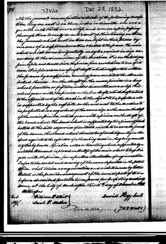
All the journals run on friction wheels of the following description, they are cast in on three inches in diameter one and a quarter inch thick more or less, and run on a pin passing through them loosely so as to admit of their turning on them. The journals which bear on them are kept in their places by means of a cast iron or iron bolted to the frame. The main wheel which turns horizontally, may be varied in size according to the dimensions of the machine, it is on the best principle, and should drive the pinion five revolutions to one of its own, it is placed on an upright shaft which is supported within the frame by a cast piece, running from one sill to the other and locked thereon. On the shaft of the main pinion is a key wheel fourteen or fifteen inches diameter more or less, this wheel gears with the pinion on the line shaft, which shaft extends to the opposite end of the machine to the object to be propelled, and is supported by the cast sills. On the end next to the machine to be propelled is a key wheel of the same size as the one on the shaft of the main pinion, which gears with a pinion on the shaft of the band wheel. The band wheel is supported by two pieces of plank bolted to the sills edges wise of suitable width to receive the journals of the same, this band wheel should be of such size as to give the speed required to the cylinders of a threshing machine, they being connected together by bands. A friction roller or travelling wheel, supported by a suitable standard is placed on the top of the main wheel to keep it in gear with the pinion, for a further illustration of my invention I refer to the model and drawing of the same deposited in the Patent Office. What I claim as my invention and wish to secure by letter Patent is the peculiar arrangement of the several parts of the so before described portable horse power for propelling machines done at the City of Washington this 15th day of December 1832.
Witnesses
William R. Elliot
Samuel D. Mather
David Flagg Smith
(703 words)
Published accounts: journal notice
Notice in the monthly list of patents, with remarks
Journal of the Franklin Institute, new ser., vol. 11 (1833), p. 384 · View the page
32. For a Portable Horse Power, for propelling machinery; David Flagg, jr. city of New York, December 28.
Remarks. The claim made in this patent is to "the peculiar arrangement of the several parts of the portable horse power, for propelling machinery." This machine has one merit at least, in not claiming to gain power, as is the case with several of its predecessors. A vertical shaft is to be turned by a lever to which a horse is attached. The peculiar arrangement consists of the wheels, pinions, and shafts, by which the motion is communicated below, instead of above, the horsewalk. We suppose that it is from this construction that it derives the name of portable, as it occupies less space than the common horse mill, and may therefore be more readily packed up, and transported to a distance.
About this record
- Patentee
- DATAMP
- Date
- the Name and Date index of patents, DATAMP, USPTO records
- Invention
- DATAMP
- Listed in
- the Name and Date index of patents, DATAMP, USPTO records, Jim Shaw's X-patent list, the Journal of the Franklin Institute, Burke's List of Patents (1847)
- Burke's 1847 Patent Office list gives the same patent.