

Drawings and documents
USPTO scan
The patent as scanned by the USPTO
-
 Page 1
-
 Page 2
-
 Page 3
-
 Page 4
-
 Page 5
-
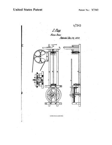 Page 6


U.S. Patent and Trademark Office · Google Patents
Show the transcription Hide (1,410 words)
Machine transcription (LightOnOCR) of the pages as scanned by the USPTO, most of them the handwritten copies made when the records were restored after the 1836 fire. Not checked; it can misread handwriting, so compare it with the scan.
Page 2.
United States Patent
Patent No.: X7343
David Hagg, junr.
Letters Patent
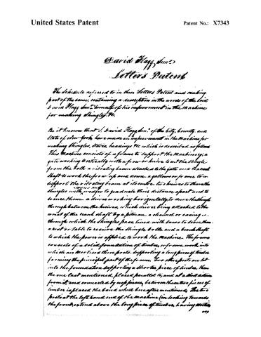
The schedule referred to in these Letters Patent and making part of the same, containing a description in the words of the said David Hagg, junr. himself of his improvement in the machine for making shingles, &c.
Be it known that I, David Hagg, junr., of the city, county, and state of New York, have made an improvement in the machine for making shingles, staves, headings, &c., which is described as follows:
This machine consists of a frame to support the machinery; a gate working vertically with a fro or knife to cut the shingle from the bolt; a vibrating beam attached to the gate and to a crank shaft to work the fro up and down; a gallows or frame to support the vibrating beam at its center; two knives to shave the shingles with wedges to graduate their distance apart and to secure them; a drive working horizontally, to drive the shingle through between the knives, which drive being attached to the wrist of the crank shaft by a pitman; a channel or casing, through which the shingles pass, lined with bars to bore them; a seat or table to receive the shingle bolt; and a crankshaft to which the power is applied to work the machine. The frame consists of a solid foundation of timber, or frame work, into which are mortised three posts supporting a long piece of timber forming the principal part of the frame. Two other posts are let into the foundation supporting a shorter piece of timber, than the one last mentioned, placed parallel to, and at a short distance from it, and connected by roof pieces, between these two pieces of timber is placed the board which hereafter mentioned. The two posts at the left hand end of the machine (in looking towards the front), extend above the long piece of timber, having mortises
017
Page 3.
United States Patent
Patent No.: X7343
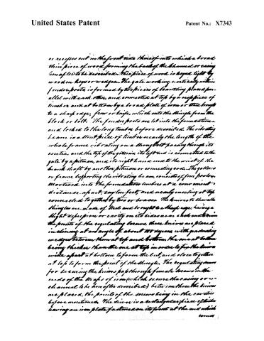
or recesses out in the front side thereof into which a broad thin piece of wood forming the back of the channel or casing hereafter to be described. This piece of wood is keyed tight by wooden keys or wedges. The gate working vertically within fender posts, is formed by two pieces of beavelling placed parallel with each other, and connected at top by a single piece of timber and at bottom by a broad plate of iron or steel brought to a sharp edge, frow or knife, which cuts the shingle from the block or bolt. The fender posts are let into the foundations, and locked to the long timber before described. The vibrating beam is a stout piece of timber nearly the length of the whole frame vibrating on a strong bolt passing through its centre, and the top of the gallery, its left end is connected to the gate by a pitman, and its right hand end to the wrist of the crank shaft by another pitman or connecting rod. The gallery or frame supporting the vibrating beam, consists of four posts, mortised into the foundations timbers at a convenient distance apart, say ten feet, and nearly meeting at top connected together by ties or braces. The knives to shear the shingles are made of steel and brought to a sharp edge, having a slight depression or cavity on its sides near each end from the points of the regulating screws. These knives are placed in slings at an angle of about 45 degrees, with graduating wedges between them at top and bottom, the one at bottom being thicker than the one at top in order to fix the knives wide apart at bottom, to form the cut, and close together at top to form the point of the shingle. The regulating screws for securing the knives pass through female screws in the ends of the strips of iron (which secure the casing or channel to be hereafter described) between these the knives are placed, the points of the screws being in the centres before mentioned. The die or is a rectangular piece of steel having an iron plate fastened on its front at the end which
200004
Page 4.
United States Patent
Patent No.: X7343
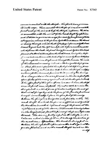
comes in contact with the shingle. This plate has a groove on its outer edge. There are also two strips of iron secured to the front end of the drive to keep the shingle in place. The drive is connected with the wrist of the crank shaft by a pitman and it slides in grooves on ways formed by four pieces of timber set edgewise, secured to the frame by bolts and screws. The channel or casing through which the shingle passes is formed by the front board keyed into the left hand posts before mentioned, and which forms the back, the front being formed by two thin boards placed at a short distance from the back board, having thin strips of iron between them and the back at top secured by screw bolts passing through the iron strips and through the boards. The inside of this channel or casing is lined with horizontal strips of iron or steel placed in parallel lines, part of each strip being plain and part being cut into saw-teeth to score the shingle as it passes through the channel previous to its meeting the knives. Two iron guides or bars are placed in the lower part of the open space of the casing against which the shingle both rests, and the upper part of this open space is a saw to score the shingle near its point near the point. The rest or table to receive the shingle bolt is a thick piece of timber resting on the ends of two vertical springs keyed to the face of the founder posts and brought immediately before the open part of the casing. Between the springs is a horizontal anti-friction roller. The crank shaft to which the power is applied and by which the machine is worked is placed across the frame at the right hand end of the same, its journals turning in boxes on the longitudinal parallel pieces of the frame before mentioned. The driving pulley is put on this shaft, and a balance wheel is also put on it to steady the motion of the machine. Operation—The machine being put in motion the shingle bolt is placed on the rest against the guide plates, and as the crank shaft revolves the end of
Page 5.
United States Patent
Patent No.: X7343
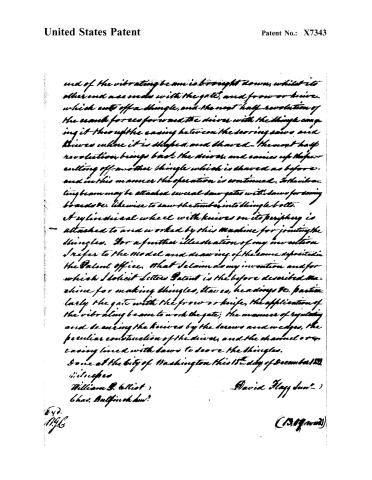
end of the vibrating beam is brought down, whilst its other end ascends with the gate, and from or knife which cuts off a shingle, and the next half revolution of the crank forces forward the driver with the shingle carrying it through the casing between the sawing saws and drivers where it is shaped and shaved. The next half revolution brings back the driver, and carries up the preceding off another shingle which is shaved as before, and in this manner the operation is continued. To the vibrating beam may be attached several saw gates with saws for sawing boards &c. likewise to saw the timber into shingle bolts.
A cylindrical wheel with knives on its periphery is attached to and worked by this machine for jointing the shingles. For a further illustration of my invention I refer to the model and drawing of the same deposited in the Patent office. That I claim as my invention and for which I solicit Letters Patent is the before described machine for making shingles, staves, headings &c. particularly the gate with the frore or knife, the application of the vibrating beam to work the gate; the manner of regulating and securing the knives by the screws and wedges, the peculiar construction of the driver, and the channel or casing lined with saws to saw the shingles.
Done at the city of Washington this 18th day of December 1850.
Witnesses
William B. Elliot
Chas. Bulfinch
David Haydn
(307 words)
E.Y.D.
11.9.6
Page 6.
United States Patent
Patent No.: X7343
D. Flagg,
Horse Power.
Patented Dec. 28, 1832.
X7343

ALL PHOTO-LITHO. CO. N.Y. (FISHER'S PROCESS)
Published accounts: journal notice
Notice in the monthly list of patents, with remarks
Journal of the Franklin Institute, new ser., vol. 11 (1833), p. 384 · View the page
31. For a Machine for making Shingles, Staves, Heading, &c.; David Flagg, jr. city of New York, December 28.
Remarks. This machine is intended to be driven by a water wheel, a crank from which works a lever beam, carrying at its opposite end a frame, sliding between fender posts, to which frame a knife, or frow, is attached, which cuts the shingle from a bolt firmly secured upon a bed. The shingle, when cut, is forced edgewise between two knives, by means of a follower. To give the proper taper to the shingle, the knives are nearer together at one end than they are at the other. Fixed saws are used to score the shingle crosswise, which shortens the shaving, and thus enables the knives to shave it readily. These operations, or, rather, the means of performing them, are not clearly described, and, in fact, the details of the whole machine are in many points obscure. The claim is to the machine generally, and to the vibrating beam to work the gate; the latter with its frow, or knife; the mode of securing the knives; the peculiar construction of the driver; and the saws used to score the shingles. :
About this record
- Patentee
- DATAMP
- Date
- the Name and Date index of patents, DATAMP, USPTO records
- Invention
- DATAMP
- Listed in
- the Name and Date index of patents, DATAMP, USPTO records, Jim Shaw's X-patent list, the Journal of the Franklin Institute, Burke's List of Patents (1847)
- Burke's 1847 Patent Office list gives the same patent.