

Drawings and documents
National Archives restored drawings: drawing
Stephen H. Long's Patent Drawing for a Method of Constructing Wheels for Locomotive Engines and Other Railway Carriages


National Archives, Restored Patent Drawings (Record Group 241) · Full-size scan at the National Archives · Catalog record
Show the text on the drawing Hide (581 words)
Words on the drawing as machine-read by the National Archives; not checked. Useful mainly for searching.
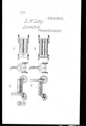
Sheet 1. which Method of constructing wheels for Locomotive Engines and other Rail-way Carriages, as iontemplated in the / 7th Paragraph of my patent for "Improvements in the Locomotive Heamsongine and other rail- road carriages; dated Dee*28 1832. / years -Heleehable / Reev Almol. 10 lune 1844. 250 / Fig.2. / Restored Patint, dated Dec. 28th. 1832. See / th / claim / Fig.1. / vol. 14. p- 238 / Fig / Stephen H.T.ong / Car Whule- / Fig 3. / 106 RAILWAYS. / CHA / Go, / 3. Exterior Mountings & Fittings / [122] Wheels. / 7357 / no / So. / FO / MM / 7351X / O/ / ПО / di / FO / e, / 50 / cl / 508 / E' / E. / no / See VII / On / OR / FO / E' / rp / JI / no / Γp / On n / nO / 0n / B. / mp / Ga / On / On / c&g / Go / c&g / Explanations of the Drawings / Fig.1. Insid view of the Wheel. Fig. 2. butside view of the What. Fig.3. Edgwise view of hoo spokes without their Hanges. Ing.4. side view of two spokes with their Hungs He / A.B. The whee-him; inside view.- C.D. The wheel Rim; outside view.- a.a. The exterior or main whal Hange.- The interior wheel Hanye. C.C. for the ends ofthe Speaker / EE. The Spokes with their ribs Hungs Ve. d.d. The Spoke ribs. ee. The Spoke flanger. F.F. The what Hub sig.,Ihe ends of the spokes adapted to the receptaily C.C. nn. Bolts or / Airts, confining the ends of the spokes to the Whal-kim. / Done at May 26. 1844. / Shphin H. Long.
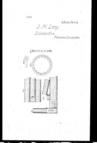
Sheet 2. I late III / [t8] / 88T / hephen Long / LOCOMOTIVES. 8. / 7351.X / Intented I. / STEAM. / of / Sig.ii / Ty.10. / highest level / Section. / Re ferences to the Free Pump Article IV. o.iy.10. / a. the boiler / b. the chimney. / C. hallow cylindu capedon both ends. / Inferences to the she Pump. / d supply cack shut. / a the boiler / e steam cock shut. / b the chimney / fe draft cock.and hose .g. open. / h ejection pipe / C hallow cylinder Caped on both ends. / cylinder / d supply cock. / l Iteam cack. / h casing. / l pipe for waste Iteam. / of draft cock, and hose g. / l' the Jame leading into the chimney 6. / h injection pipe. / m pipe leaving the water to the useroin. / i cylinder / h casing. / l pipe for waste steam. / L' pipe for the waste steam paping through / cylinder i. / m Dom / n pipe for waste steam leading to then / o. pipe chimney. leading the condenced iteam to the / Reservoir:
Sheet 3. Suphin HLong / Improvements in Locomotions Iteam Engine ano'other Praitread / 123. STEAM. / 3. LOCOMOTIVES. / [94] Locomotives / Val. M. by. 233 / Plate / #6= / Patentio Dec. 28. 1832. / CLASSIFICATION / betion. / 7351-4 / DIVISION / of / Fig.). Section / Fig Jig.2. Front view. / Fig.3. Topriew / Plate I Boilers & flew. / late II. bilers with movemble chimneys.,Swhel. / Plate III free Pump. / 6. / +++ / Tig.4. Section / Tig 5. Frontview / on / Jig. 6. Top view. / Preferences a.a boiler see Ty.1. 2 x 3. bb. the fever. c fire place. d direbrick. e. chimney. / Patent affice Maroh 11. 1842 / a a a boiters. b fine place. c. scapsione d. chimary. see Sip s.x.b. / Marbunder the direction of they Commissioner afratents / in conformity with ret of w march 1837 / Commiteroner of atents.
Sheet 4. Plate II. / CLASSI richard / Stephen Longs Locomotion & / 7351.4 / [+6] / Copview. / Patents I. 28. 1832. / division. / 3. LOCOMOTIVES. / 123. STEAM. / sty.,14. / Jigg / ol / fg.12. / fig.8. / ofis.y / of / oiR / be / Section / Hights. / Section / Side view, / References. by. 7.889 aaa three briters. / 6 the flue C Toap stone. d moreable chimmy. / e hinge. f escape steam pipe. / sky. th. 13xia. what. a. / brim. c flange C.C.C. & receptaches for spocker / Sign. hub & spooke seperately.
USPTO scan
The patent as scanned by the USPTO
-
 Page 1
-
 Page 2
-
 Page 3
-
 Page 4
-
 Page 5
-
 Page 6
-
 Page 7
-
 Page 8
-
 Page 9
-
 Page 10


U.S. Patent and Trademark Office · Google Patents
Show the transcription Hide (2,949 words)
Machine transcription (LightOnOCR) of the pages as scanned by the USPTO, most of them the handwritten copies made when the records were restored after the 1836 fire. Not checked; it can misread handwriting, so compare it with the scan.
Page 1.
7351X
3 Sheets-Sheet 1.
S. H. Long,
Locomotive.
Patented Dec. 28, 1892.

Page 2.
7351X
3 Sheets-Sheet 2
S. H. Long.
Locomotive.
Patented Dec. 28, 1892.
Fig. 1
Fig. 2
Fig. 3
Fig. 4
Fig. 5
Fig. 6
Fig. 7
Page 3.
7351X
3 Sheets-Sheet 3.
S. H. Long,
Locomotive.
Patented Dec. 28, 1892.
Page 4.
7351x
Stephen A. Long
Letters Patent
The Schedule referred to in these Letters Patent, and making part of the same, containing a description in the words of the said S. A. Long himself of his improvement in the Locomotive steam Engine and other Rail Road Carriages.
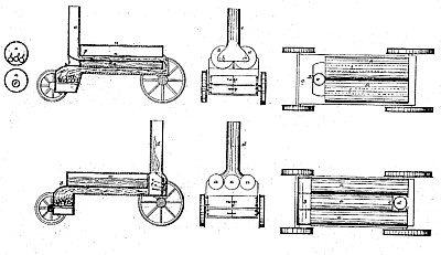
The application and use of two parallel cylindrical boilers placed horizontally on the carriage and lengthwise thereof with one or more horizontal flues passing longitudinally through each boiler in the lower half thereof, which flues must be of a size sufficient to convey the heated air, flame, &c. from the fire place to the chimney, both of which, in this case, are situated at the same end of the boilers. The fire place is located beneath the boilers and has its sides and front formed of sheet iron suitably lined or luted with fire brick or clay, and in its rear sides above a bridging of brick or clay, stone, and opens into a broad flue of the entire width of both boilers, the side bottoms and back ends of which are constructed of sheet iron suitably formed and appropriately lined or luted with fire brick or clay. The boilers themselves constitute the roof or upper side, not only of this broad flue but also of the fire place at the back end of the boilers. The broad flue communicates with the flues leading through the boilers. This mode of construction is believed to be entirely new in its application to Locomotive Steam Engines.
In this item I claim the application of two horizontal cylindrical boilers with two or more flues in each passing longitudinally through them, the fire place being anterior of the boilers and beneath them, a simple boiler of similar construction having previously been employed by Oliver Evans in the construction of a locomotive engine and by others for other purposes.
II. The application and use of three parallel cylindrical boilers placed horizontally on the carriage and lengthwise thereof with one or more horizontal flues passing longitudinally through each boiler in the lower half thereof, which flues must be of a size sufficient to convey the heated air, flame, &c. from the fire place to the chimney, both of which, in this case, are situated at the same end of the boilers. The fire place is located beneath the boilers and has its sides and front formed of sheet iron suitably lined or luted with fire brick or clay, and in its rear sides above a bridging of brick or clay, stone, and opens into a broad flue of the entire width of both boilers, the side bottoms and back ends of which are constructed of sheet iron suitably formed and appropriately lined or luted with fire brick or clay. The boilers themselves constitute the roof or upper side, not only of this broad flue but also of the fire place at the back end of the boilers. The broad flue communicates with the flues leading through the boilers. This mode of construction is believed to be entirely new in its application to Locomotive Steam Engines.
In this item I claim the application of three horizontal cylindrical boilers with two or more flues in each passing longitudinally through them, the fire place being anterior of the boilers and beneath them, a simple boiler of similar construction having previously been employed by Oliver Evans in the construction of a locomotive engine and by others for other purposes.
Page 5.
without flues leading through them. The latter mode being preferred when the diameter of each boiler does not exceed fifteen inches. The fire place in this case also is located at one end of the boilers & occupies a width equal to nearly 2/3 to that of the three together. The front and rear of the fire place are formed of sheet iron appropriately braced and stiffened and lined with fire brick or clay as before. In rear of the fire place is a bridging of brick or Soap Stone, as before mentioned, above which the fire place communicates with a broad flue of appropriate depth & of a width equal to that of the four boilers or to the entire width occupied by the three boilers. The side bottom and rear of this flue are constructed of sheet iron or copper and appropriately lined with fire brick or clay. Its roof is formed of the three boilers, which have their entire under surface or three portions of their entire surface situated below a horizontal plane passing through their centres exposed to the action of the heat generated in the fire place.
The middle boiler of the three is shorter by about one foot than either of the outside boilers in order to afford a communication from the broad flue into the chimney which is perpendicularly from the back or rear end of the middle boiler & between the other two boilers. A direct passage from the flue into the chimney is intercepted by a tile of fire clay or slab of Soap Stone which compels the heated air to pass round the extremities of the tile and immediately under the back ends of the exterior boilers before it can enter the chimney which is immediately back of the tile. For many particulars in regard to the relative dimensions of the grate and the best mode of constructing furnaces for Steam Engines I am indebted to the liberality and intelligence of James Watt Engine of Philadelphia, but their application and use in the construction of Pneumatic Engines. I claim for myself as new and useful. In this Patent I claim the application of three horizontal cylindrical boilers (with or without flues leading through them). The fire place being exterior of the boilers and beneath them. Similar boilers having been previously employed by myself.
Page 6.
and others for other purposes. I also claim the manner of construction specified in the item—although as stated therein I am indebted to Mr. Aitken for much useful information which enabled me to regulate the dimensions of the various parts as exhibited in the Pennsylvania Locomotive.
III. Another mode of constructing a swivelt or movable chimney & its application to locomotive Steam Engines which is as follows Viz. The Chimney rises in a square form through the space provided for it as stated in the preceding item of this Supplement to the height of two or three feet above the upper edge of the tile or refractory slab before mentioned. This portion of the chimney is sufficiently large to receive a lining or lining of fire clay to protect it against the heat and serves as a pedestal or basement for the swivelt or movable part of the chimney—which is round and is connected with the pedestal by means of a hinge or joint on which this part of the chimney traverses in such a manner as to admit of its being laid horizontally upon the carriage or erected perpendicularly as occasion may require in passing under Bridges, through tunnels &c.
Note.—The waste steam of the working cylinder is conveyed by a tube or pipe into the basement of the chimney into which it is injected perpendicularly from the tube in order to increase or accelerate the draft through the fire place flue and chimney.
I claim in this item the application of a movable or swivelt chimney differing from that described in the 3d item of my specification of June 1831, in having but a single oscillating joint instead of two lateral swivel joints as specified in that instrument.
IV. 2d. An apparatus intended as a substitute for the force pumps of ordinary Engines and for the purpose of supplying the boilers of locomotive & other Steam Engines with water, which apparatus I shall designate by the appellation of fire pumps inasmuch as it is calculated to perform the functions of a supply pump without the aid of any external force except in so far as it may be needed in the turning of cocks—The fire pump consists of a hollow cylinder wrapped at both ends and made steam tight, to be located
Page 7.
in such a position that the lowest part of its cavity shall be elevated at least as high as the upper surface or greatest height of the water in the boiler to which the pump is attached. The lowest part of the pump or cylinder must communicate with the boiler at a point or points below their water surface by means of a pipe or tube of suitable size furnished with a stop cock or valve denominated the supply cock which may be opened or shut at pleasure. The uppermost part of the pump or cylinder must also communicate with the boiler at a point above their water surface by means of a tube or pipe (which may be considerably smaller than the former) furnished with a cock or valve to be called the steam cock by means of which tube and cocks steam from the boiler may be conveyed into the pump at pleasure. The pump must also communicate with the water cock tank or reservoir by means of a tube pipe or hose furnished in like manner with a stop cock or valve to be called the draft cock for the purpose of opening and shutting this communication at pleasure. Moreover a small cock or valve to be called the ejection cock must be applied to the pump in some convenient position for the purpose of discharging the steam from the pump whenever there is occasion to replenish it with water. The steam thus discharged may be conveyed through a pipe to the steam chest attached to the working cylinders, instead of being waste, may be made to contribute to the operation of the engine. The operation of the fire pump is as follows: Let the supply cock and steam cock be shut, open the ejection cock and also the draft cock and the water will freely flow from the reservoir (which is supposed to be higher than the pump) into the pump. When the pump is full of water or sufficiently so, shut the ejection and draft cocks and then open the steam cock and afterwards the supply cock and the water will flow as freely from the pump into the boiler through the supply tube its place in the pump being occupied by steam from the boiler. The operation may
Page 8.
Dec 28, 1832
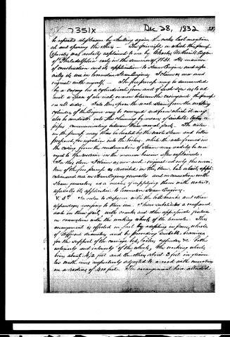
be repeated at pleasure by shutting again the cocks last mentioned and opening the other. The principle on which this pump operates was verbally explained to me by Charles Wetherill Esq. of Philadelphia early in the summer of 1831. His manner of construction and its application to Steam Engines, and especially its use in locomotive Steam Engines, I claim as new and original with myself. The free pump may be surrounded by a casing in a cylindrical form and of such size as to admit a space of one inch or more between the casing and the pump on all sides. Into this space the waste steam from the working cylinder of the engine may be conveyed and from which it may also be conducted into the chimney by means of suitable tubes or pipes communicating between these several parts. The water in the pump may then be heated by the waste steam and better prepared for injection into the boiler, while the water formed in the casing from the condensation of steam may readily be conveyed to the reservoir in the manner herein after explained.
In this claim I claim as new and original not only the invention of the free pump as described in this claim, but also its application and use in steam engines generally and in connection with steam generators as a means of supplying them with water, especially its application to locomotive Steam Engines.
V. 5th. In order to dispense with the bell cranks and other appendages necessary to their use, I have substituted a compound axle in three parts with cranks and other appropriate fixtures in connection with the working wheels of the locomotive. This arrangement is effected in part by adopting in pairs, wheels of different diameters and by providing suitable bearings for the support of the carriage bed, boiler, cylinder, &c. both exteriorly and interiorly of the wheels, the working wheels being about 4 1/2 feet and the other about 3 feet in diameter, the wheels being respectively adjusted to a road with curvature on a radius of 400 feet. The arrangement here alluded
Page 9.
together with the leading improvements contemplated in this specification are mostly to be exemplified in the model deposited in the Patent Office.
VI. 6th. A method of heating the water within the force Pump by means of the waste steam and of preventing from the water thus condensed from said steam by intercepting its discharge or its passage from the force pump into the chimney or atmosphere. This method consists in the injection of the waste steam first into the casing by which the pump is surrounded, then vertically into a sort of stove attached to the upper part or side of the casing into which stove the steam enters through a tube rising from the lower level of the concavity of the casing passing into it by through the force pump and penetrating nearly to the top of the stove and then either into the chimney or open air through a tube passing out of the stove at a point about midway between its top and bottom. The water that may have been formed by condensation and collected in the lower part of the casing will thus be carried upward by the steam through the vertical tube leading through the pump and be deposited in the stove, whence it will be conveyed through a tube leading from the bottom of the stove and steam into the reservoir for future use.
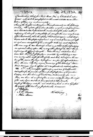
VII. 7th. A further method of constructing wheels for locomotives, gears and other rail way Carriages differing from that described in the first item of my specification of June 1831, in the following particular terms viz. The iron together with its flanges is cast separately from the hub and spokes and is furnished with cast metal adaptors to the reception of the railroad axletrees of the locomotive which the latter are inserted and held fast by means of troughs or clamps embracing the ends of the spokes and confining them to the outer flange of the iron. The spokes have a taper from beam to rim so as to fit securely from the hub. In all other respects the spokes and hub may be similar to those of the wheel described in my specification of June 1831, before alluded to. This mode
Page 10.
of constructing wheels for Rail Road Cars is believed to be entirely new and will be exemplified in this model intended as an illustration of them very imperfectly.
Among the benefits resulting from this improvement are the following namely—The intricate parts above considered may be made of such iron as is best calculated to facilitate the construction of the wheel without impairing its strength or durability, for example the rim may be made of fine hard metal while the spokes and hub which require much strength in order to their proper adjustment may be made of iron much softer and more susceptible of being wrought with ease and dispatch. The rim may be case hardened or cast in a while without producing an injurious strain upon this or any other part of the wheel thereby impairing its efficient strength—When the rims shall have been worn out they may effectually be renovated by substituting a new iron in connection with the old spokes and hub which from the nature of the service they have to perform are far less exposed to wear than the rims. By this means the wearing of the Wheels of Rail Road Carriages may be effected at a comparatively moderate expense.
VIII. 8th. The successful application and use of Anthracite coal as fuel for the generation of steam for the propulsion of Locomotive Engines and the trains of loaded cars continuously for more than one hour at a speed of ten or more miles per hour the weight of the entire train and load being equivalent to that of the weight of the engine and the rail road being level or at a slight ascent the weight of the load being proportionably increased.
J. M. Weygand
e. J. G. Brown
John Brown
J. H. Long
Published accounts: journal notice
Notice in the monthly list of patents, with remarks
Journal of the Franklin Institute, new ser., vol. 11 (1833), p. 386 · View the page
41. For an improvement in the Locomotive Steam Engine, and other rail-road carriages; Colonel Stephen H. Long, of the United States engineer corps, city of Philadelphia, December 28.
Remarks. There are several different items presented in the specification of this patent, but most of them are described in such terms as to leave the engineer who shall attempt the construction of an engine from the account given of it, a great latitude of means, and to require the aid of some inventive genius on his part. Where this is the case the things claimed ought to be essentially new in principle; as the particular mode of combining and arranging certain parts, which constitutes the only novelty in many machines, is not relied on. Notwithstanding the known talents and judgment of Colonel Long, we apprehend that some of the things patented by him will not be found to possess all that novelty in principle which will form a secure basis for a patent. The specification is of considerable length, and we are not willing to dismiss it with that kind of brief analysis to which we in general confine ourselves. The boilers of his engine, which are the first things described, consist of two horizontal cylinders, with one or more flues passing through them, the fireplace being exterior to, and below the boilers. Oliver Evans, it is observed, employed a single boiler of this construction in his steam engine, and others have since applied them to different purposes; but "this mode of construction is believed to be entirely new in its application to locomotive steam engines." We much doubt whether this application of what was previously known, constitutes such an invention or discovery as is contemplated by the patent law. If it constituted a part of an existing patent, it could not be used, and if it belonged to an expired patent, or made part of a known invention, it cannot be incorporated in a new patent, although any specific improvement upon it may be. A boiler consisting of three cylinders, without flues through them, is next claimed; this kind is preferred when the diameter of the cylinder is not more than fifteen inches. The fireplace and broad flue are similar to those employed with the first named boilers, but the chimney, in this latter construction, must be placed at the back end of the boiler. The middle boiler of the three, is made a foot or so shorter than the others, to admit a square flue to connect with the round switch flue above it. A slab of soap stone, or some similar article, is used to intercept the heated air in its passage into the flue, and to compel it to pass immediately under the back ends of the exterior boilers. The three boilers, thus constructed, form the second claim. The moveable switch chimney used in this engine, is made to turn on hinges, so that it may be laid horizontally in passing through tunnels, &c. This, it is stated, differs from the chimney described in the 4th item of the patentees' specification of June, 1831, in having but a single, instead of two oscillating joints. A substitute for the force pump of ordinary engines is next claimed; this is designated the free pump. It, however, is more properly a reservoir, which is intended to contain water to supply the boiler. This reservoir, or vessel, is situated above the boilers, is closed at top by a dome, and has two tubes leading into it from the boilers, one of them entering into it at top of the reservoir, and admitting steam, the other passing down and communicating with the water in the boilers. Each tube must have a cock, or valve, to open or close it. Water may be admitted into this steam-tight reservoir, and may be heated there, by allowing waste steam to enter a casing by which it is surrounded. When this supply water is to be admitted into the boiler the cocks of both tubes must be opened, and the contained fluid being subjected to equal pressure both above and below, it will flow freely into the boilers. The patentee states that the principle of this apparatus was described to him by Charles Whetherill, Esq., of Philadelphia, in the summer of 1831, but that he claims the manner of construction which he has described, and especially its use in locomotive engines. For whatever of novelty there is in the arrangement adopted by Colonel Long, he is fairly entitled to a patent as an improvement. The principle of allowing water to flow from a reservoir into a boiler by equalising the pressure upon its upper and lower surface, we have known for several years, and cannot now tell where we first learned it. In order to dispense with the bell cranks and their appendages, Col. Long states that he has made a compound axle, in three parts; which, however, he has not described, nor is it represented in the drawing; but the model deposited in the patent office is referred to as an exemplification of it. As the model forms no part of the legal description of a patent, and cannot be published, we make it a rule to depend upon the specification and drawings in preparing our analysis, and cannot, from them, give any account of this part of the invention. A method of heating the water in the free pump, by means of the waste steam, and of preserving the heated water resulting from this steam, is next described, not however with reference to any specified construction of the apparatus employed, but only in that general way of which we have before spoken. A different mode of constructing the wheels from that indicated in the specification of June, 1831, forms the next item in the present patent. The model is here again referred to for an exemplification; but we are informed that the wheel is to be made in part of iron, and in part of wood, the rim, together with its flanches, being cast separately from the hub and spokes, with parts formed upon it to receive the latter, which are to be held fast by bolts, clamps, &c. The spokes are to narrow down as they recede from the hub, but in other points are to be like those described in the specification of June, 1831. The last claim is to "the successful application and use of anthracite coal" in locomotive engines; nothing, however, is said respecting the mode in which this successful application is effected. We are told merely that it has been used continuously for more than one hour, at a speed of ten miles or more in that time, and with a weight in a train of cars equivalent to five times that of the engine, the road being level, but that the speed will be proportionally decreased should the load be augmented. If Colonel Long has succeeded, with the ordinary draft, in applying anthracite so as to answer for fuel in long trips, a great desideratum has been obtained by him, as all previous attempts have entirely failed. The difficulty of using this fuel in a locomotive, arises from the coal packing down, in consequence of the continued vibration to which it is subjected, which packing very soon stops the ordinary draft through it. To stir it up will not remove this difficulty, as those who have burnt anthracite well know; it being all important that the pieces of coal, when ignited, should preserve their relative positions. By means of an artificial blast air enough may be forced through the coal, notwithstanding the packing; and we know of no other means by which it can be effected. This was first accomplished, we believe, by Mr. Phineas Davis, on the Baltimore and Ohio rail-road.
DATAMP: illustration
Illustrations from DATAMP

DATAMP (Directory of American Tool and Machinery Patents), via the Internet Archive · Archived DATAMP page
About this record
- Patentee
- DATAMP
- Date
- the Name and Date index of patents, DATAMP, USPTO records
- Invention
- DATAMP
- Listed in
- the Name and Date index of patents, DATAMP, USPTO records, Jim Shaw's X-patent list, the Journal of the Franklin Institute, Burke's List of Patents (1847)
- The Name and Date index lists this patent twice.
- Burke's 1847 Patent Office list gives the same patent.
Shaw: also: Long, S. H. 1832-12-28