

Drawings and documents
USPTO scan
The patent as scanned by the USPTO
-
 Page 1
-
 Page 2
-
 Page 3
-
 Page 4
-
 Page 5


U.S. Patent and Trademark Office · Google Patents
Show the transcription Hide (2,393 words)
Machine transcription (LightOnOCR) of the pages as scanned by the USPTO, most of them the handwritten copies made when the records were restored after the 1836 fire. Not checked; it can misread handwriting, so compare it with the scan.
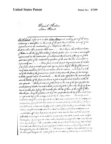
Page 2.
United States Patent
Patent No.: X7399
Daniel Newton
Letters Patent
The Schedule referred to in these Letters Patent, and making part of the same, containing a description in the words of the said Daniel Newton himself of his improvement in the construction of a Blapboard Machine.
To all to whom these presents shall come: . . . Be it known that I Daniel Newton of Dalton in the County of Coos & State of New Hampshire have invented a new and useful improvement in the construction of a Blapboard Machine, and the following is a full & exact description of the construction & operation of the said Machine as invented or improved by me. . . . First, a frame is made 20 feet long & 5 feet wide; the timbers of the frame about 7 or 8 inches square & the legs one foot in length. The legs of the forward end of said machine (that is the end towards which the sawmen must be put on to the end of the timbers of the frame & come about 8 inches above the frame for the carriage to strike against when it runs back. . . . On the side opposite to the saw & prefixed to the timber of the frame is a board 14 feet in length, & about 6 inches in width, the side upwards. . . . At the forward end of this board on the side of the leg is prefixed two small pieces of timber—one inch & thick, 7 inches long & two inches wide, hanging by an iron or wooden pin passing thro’ 2½ inches from the top of them, so the weight of them below the pin, being the greatest, will keep them perpendicular; the top of them must come as high as the top of the carriage & about 1½ inch between them. . . . On the top of this board to the end of it in a line against the center of these small pieces of timber, hanging perpendicularly, is a piece of timber 2½ inches at the forward end & 1½ inch at the other end & 1 inch thick at the middle end, beginning at the middle of the thickness on each side, a line is drawn straight to the center, where it meets at the distance of about 9½ inches; this wood must be taken off to these lines; & from the point where these two lines meet the remainder of the stick, one & a half inch in width, the narrow end of this stick must be made nearly in the same form, beginning on the sides as above directed & running to the center, where they meet about six inches from the end & between these two points, the timber is cut, & the thickness is at the ends. This is hung by a pin passing thro’ it & the board on which it lays at the distance of 7 inches from the middle end. . . . On the frame or platform before described running the whole length thereof & on the middle of the timbers are pieces of cast iron 3½ inches thick, etc.
Page 3.
United States Patent
Patent No.: X7399
The underside 3/4 of an inch wide, running almost to an edge on the upper side, with small bars across on the under side 3 inches long, within 3 feet of each other, through which screws are put to hold the iron on to the timbers. On this platform is a carriage 15 feet long, made in the following manner. The sides & ends are to be timbers about 6 inches square, they may be blocked together by cutting 4 into each, about 6 inches from the ends of the side pieces & beginning on the end of the cross pieces, which are next to the sams & from the end of the cross pieces on the other side must be left about 6 inches projecting over from the side, into which is cut at each end of the carriage 1 inch 3/4 inch wide & 3/4 of an inch deep, & into these grooves are placed two pieces of timber about one inch & a quarter square & 15 feet long, placed in such a form that they will come regular against those of timber hanging perpendicular at the forward end of the carriage. At the hindmost end of the carriage on the under side of the 6 inches which projects over of the cross piece & in the centre of the same, is so fixed the end of a timber about 3 inches thick & 2 inches & the length must be exactly to reach; when the carriage is run back against the forward end to those small pieces of timber which hang perpendicular at the forward end of the carriage against which the end of it strikes the lower end of them ultimately, by drawing over the piece of timber on the board at the forward end of the carriage. On each end of the carriage so fixed to the cross pieces about 10 inches from the side, opposite to the sams is a post bolted onto the end of the carriage, & about 1 inch square; on these two posts is hung a shaft about 15 feet long which must be straight exactly & ought to be turned; this shaft ought to be at least 1 inch in diameter. On this shaft over the center of the cross pieces at each end of the carriage is a wheel of cast iron about 10 inches in diameter completely encircled with rope; to these wheels on the side of the shaft opposite to the sams are fastened two weights so opposed to weigh about 20 lbs each, they ought to be as near the ends of the shaft as they can to prevent springing it. On the forward end of the shaft is a crank which by turning the heart block is drawn back under these two cast iron wheels, the pieces of cast iron are pieces which are called gauges, they must be about 10 feet long, 1 inch wide & 3/4 thick, with notches on the side & rope on the top, which match into those on the shaft, so, then the ends of these gauges next to the sams are fastened to the heart block, a piece of timber about 12 feet long & three inches square. Under this heart block are two pieces of timber about 6 inches by 4 which run square across the carriage, which are let down into the side pieces of the carriage about an inch, the piece of timber, which is to the hindermost end of the carriage is to be about one foot from the end piece of the end, the other is about 3 feet from this towards the forward end of the carriage; on the end of these timbers next to the sams & about 3 feet in length must be placed small timbers of cast iron or pieces of polished iron or steel; this is what the plank lays on, while drawing into ship boards & it is very important to have it iron as easy as possible.
Page 4.
United States Patent
Patent No.: X7399
On the head block are two dogs, one fastened nearly to the end of it in the near part of the carriage; the other is in a mortise 4 feet long & ¾ of an inch wide, so that it can be moved to draw from 8 to 12 feet; on one end of these dogs is a screw & a nut thereon. . . . On the side of the carriage, next to the saw & under the cross pieces about 7 inches in pieces of cast iron to the length of 14 feet which is called the rack & which must be completely fastened to the carriage. . . . This rack ought to be about 1 inch square including the cogs, with which it is to be lined on the under side. The gauges of which one end is fastened to the head block, lay on the center of the cross pieces at each end of the carriage, exactly under the wheels of cast iron on the shaft which meshes into them & the cogs on the wheels & gauges must correspond exactly with each other. . . . The notches on the side of the gauges are 1 inch & ¾ of an inch long & these two pieces of timber which are on the 6 inches that project over the carriage have grooves cut into them ¾ of an inch deep, thro. which the gauges, 10½, & one side is cut standing in such a manner that they will fit into the notches of the gauges. . . . At the forward end of the carriage & to these two pieces of timber on the under side of each is attached a wire spring one end of it is fastened to them, & the other to the cross piece of the carriage which springs keep them in the notches of the gauges. . . . On the inside of these two pieces of timber at each end of each one is prefixed a spring made of large wire or steel for the purpose of moving these timbers into the next notch of the gauges alternately. . . . These two pieces of timber hanging perpendicular at the forward end of the carriage, the board on the side of the frame, the piece of timber on the board, the piece attached to the hindmost end of the carriage which draws over the piece on the board & these two pieces with springs prefixed to them are on the same principle exactly of their total on a Single Machine with this one exception, there is an addition of 4 springs, which moves them alternately into the next notch of the gauges. . . . On the side of this frame on which the carriage runs & about 4 feet in length & beginning about 10 feet from the forward end of the carriage is a frame about 20 inches wide on which is hung 2 circular rails about 22 inches in diameter is large enough to be profitable: one hangs in a perpendicular form & the other including on the side ¾ of an inch, to every 6 inches of the diameter of the saw, the shafts or axles on which circular saws are hung are too well known to need a description; the collars on these shafts ought to be about 6 inches in diameter. . . . These two saws hang in the following position, one is directly forward of the other, excepting it is moved by the other ½ an inch, which is the hindmost one & they must be ½ an inch apart at the top of the collars & the top of the . . . . saw before described; will bring them ½ of an inch apart, 6 inches above the collars; which will leave the cleatboard ½ of an inch in thickness; or both saws may hang perpendicular one ½ inch by the other & draw both caged.
Page 5.
United States Patent
Patent No.: X7399
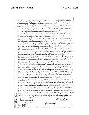
of a thickness by having another pair of gauges to put in on account of its taking more time to saw both edges of a thickness. On the outside of each saw near the hindmost edge is a piece of iron or steel to which when the end of the clefboard comes it springs it off from the saw to prevent their heating the one for the forward saw must be equally behind it & near to the edge of it... The pulleys on these shafts to which the saws are hung, must not be on equally forward of the other but by the other a little more than the width of one to prevent the belts which are around the pulleys from interfering with each other... These belts are to be around the pulleys & wound a drum underneath the floor on which the machine stands which drum is turned by water or some other power & puts the machine in operation... Near the forward end of this small frame on which the saws hang is a shaft of wrought iron which passes through the same & just under the pieces of iron on which the carriage runs... On the end of this shaft is a cast iron wheel about 14 inch in diameter, which meshes into the rack & out by which the carriage is drawn up; around this end of the shaft is a spring which would be glad to keep the cogs on this wheel wheel out of place on the rack; but this end of the shaft, every time the carriage runs back is raised 1/4 of an inch by a loop of iron or steel in the hindmost end of the carriage, which comes under the spring around the shaft & raises it on to a notch in a piece of iron, where it remains until it is moved off the same, which operation is performed by one or more pieces of iron fastened to the carriage & fixed in such a manner that they will move it off the notch when either of them comes against it; these pieces of iron may be hung in the center & a pin to alter from one side of them to the other so that any one of them may be used at any time according to the length of the plank which is sawing; there ought to be 5 beginning at 5 & ending at 10 feet... Near the other end of this shaft which moves the carriage is a wheel of cast iron about 10 inches in diameter & incircled with cogs into which a small wheel of cast iron meshes 14 inch in diameter, which turned round & thereby moves the carriage; this small wheel is on a shaft about 1/4 of an inch square, & on the other end of the shaft is a pulley around which there is a band from a pulley on the shaft on which the forward saw is hung & by the saw turning the whole machine is put in operation... On the center of the said piece at the hindmost end of the carriage is fastened a rope which runs back way to the forward end of the carriage, and goes thro the floor over a bundle at the end of which a weight is tied of suitable height to run the carriage back as it may be run back by gearing...
Witnesses: James Hatcher
Henry Bacon
Daniel Newton
(2510 words)
Published accounts: journal notice
Notice in the monthly list of patents
Journal of the Franklin Institute, new ser., vol. 12 (1833), p. 34 · View the page
40. For an improvement in the construction of the Machine for Making Clapboards; Daniel Newton, Dalton, Coos county, New Hampshire, January 31.
About this record
- Patentee
- DATAMP
- Date
- the Name and Date index of patents, DATAMP, USPTO records
- Invention
- DATAMP
- Listed in
- the Name and Date index of patents, DATAMP, USPTO records, Jim Shaw's X-patent list, the Journal of the Franklin Institute, Burke's List of Patents (1847)
- Burke's 1847 Patent Office list gives the same patent.