

Drawings and documents
National Archives restored drawings: drawing
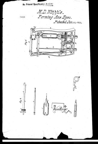
Milton D. Whipple's Patent Drawing for a Machine for Forming Axe-eyes by Drilling

National Archives, Restored Patent Drawings (Record Group 241) · Full-size scan at the National Archives · Catalog record
Show the text on the drawing Hide (32 words)
Words on the drawing as machine-read by the National Archives; not checked. Useful mainly for searching.
81. / 77. METAL WORKING, / Boring & Drilling Appliances. / $250 / 7400-X / Forming Axe-Eyes by Drilling / Patented 31-January 1833 ₫ / rig2 / Figi / 772 / C-
USPTO scan
The patent as scanned by the USPTO
-
 Page 1
-
 Page 2
-
 Page 3
-
 Page 4
-
 Page 5
-
 Page 6
-
 Page 7


U.S. Patent and Trademark Office · Google Patents
Show the transcription Hide (2,841 words)
Machine transcription (LightOnOCR) of the pages as scanned by the USPTO, most of them the handwritten copies made when the records were restored after the 1836 fire. Not checked; it can misread handwriting, so compare it with the scan.
Page 1.
No Printed Specification Available
M.D. Whipple.
Forming Axe Eyes.
Patented Jan. 31, 1833.
7400X
Fig. 1.
Fig. 2.
Page 2.
May 31, 1833
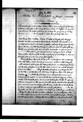
Milton D. Whipple, of Douglas, Massachusetts
Letters Patent.
The schedule referred to in these Letters Patent and making part of the same containing a description in the words of the said Milton D. Whipple himself of his improvement in the method of forming or making the eyes of axes, by drilling the same, —
To all people to whom these presents shall come
Be it known that I, Milton Dexter Whipple, of Douglas of the county of Worcester and Commonwealth of Massachusetts, mechanic, have invented a new and useful improvement in the method of making or forming the eyes of axes by drilling out the same, and that the following is a full and exact description of the construction and operation of the said machine as executed or improved by me.
The machine may be made of iron, wood, or of any material suitably strong and firm, the frame of the machine is of the form of a parallelogram, being composed of four pieces of wood or iron firmly joined together.
The part of the frame that unites the top of it is not directly over the corresponding foot at the bottom, but for the sake of convenience is placed a little back of it. At a convenient distance from the bottom of the frame, is a slot firmly screwed into the side of the frame and like that which unites or connects the sides of the frame at the bottom. Through the bottom of the frame and through this slot are two holes in each, the holes in the slot being directly over those in the bottom of the frame.
At the top of the frame and in the right hand corner as you stand facing the machine is a rod with the lower end of it resting upon a stand attached to the side of the frame at a convenient distance from the top; the upper end of this rod is confined in like manner to another stand, attached to the top of the frame and at a convenient distance from the side, so that the rod has the position of a brace, making an angle with the side and top of the frame.
To the top of this rod, the axe is confined and held firmly while the eye is drilled out. Through the holes in the slot and bottom of the frame are two bolts of iron, these are iron rods and are similar to each other and are placed upright. Bolts are movable up and down. Between the slot and bottom is a bar of iron parallel
Page 3.
with them, with a hole in each end corresponding precisely with the holes in the stock at bottom through which the steps are passed or inserted.
This bar is moveable up and down on the steps and confined at pleasure by means of screws running at keys. Through the centre of this bar, and between the steps, is a stationary screw, that is, a screw having only a revolving motion without moving forward or back. There is a thread in the central hole through the bar or screw out to receive the stationary screw, so that by turning the stationary screw, the bar which is passed through is raised or depressed according to the motion given to the stationary screw, and this screw is kept in its place or kept from rising when turned, by means of the slot.
On the left of the right hand step, rests the foot of the stock which holds the drill. Near the foot of the stock and upon it is set an endless screw, the threads of which play into or receive the leaves of a pinion wheel which will be hereafter mentioned. Above this endless screw and firmly attached to the stock is a wheel or drum for the band connecting the machine with the moving power. Above the drum is a wide slot in the stock for the convenience of putting in and taking out the Drill. Above the left of the stock to the left of the slot is a hole for the drill. This hole is not parallel with the side of the stock or perpendicular, but passes through obliquely, so that when the stock revolves, the point of the drill instead of turning on a point, describes with its point a small circle. This drill is firmly held in the stock by means of a screw, and when the drill is put into the stock, it is inserted with its most prominent cutting point directly against that part of the stock where the screw enters; and the screw is inserted centrally on the largest side of the stock.
Above the slot and on the back side of the machine and resting on bars or arms attached to both sides of the frame is a shaft upon the right hand end of which is a pinion, the leaves of which are received upon the leaves or threads of the endless screw on the foot of the stock before mentioned. Upon the opposite end of this shaft is another endless screw, moving another pinion which is attached to the lower end of an upright shaft on the other side of the frame. This upright shaft is of great length with the stock; and near the upper end of this shaft, it is so bent or crooked that when it revolves, it draws the motion more by a round. The lower end of the crooked part of this shaft describes in revolving, a larger circle than the upper part. The diameter of the larger circle thus described is great.
Page 4.
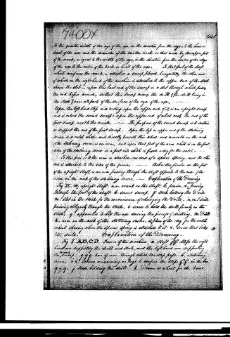
to the greater width of the eye of the axe in the direction from the edge to the head or head of the axe and the diameter of the smaller circle or that made by the upper part of the crank, is equal to the width of the eye, in the direction from the center of the edge of the axe to the center of the back or head of the axe. To that part of the shaft which opposes the crank, is attached a sweep placed horizontally, the other end of which on the right-hand of the machine is attached to the upper end of the stock above the slot—upon this last end of the sweep is a slot through which passes the rod before named, so that this sweep moves the drill (the drill being in the stock) over all parts of the surface of the eye of the axe.
Upon the left hand side and resting upon the upper end of it, is an upright sweep and is called the second sweep; upon the upper end of which rests the end of the first sweep next to the crank. The purpose of the second sweep is to sustain or support the end of the first sweep. Upon the left or upper end of the stationary screw, is a ratch wheel, and directly beneath this wheel and moveable on the neck of the stationary screw, is an arm, and upon that part of the arm which is on the front side of the stationary screw is a foot into which is fixed a dog for the ratch wheel.
To this foot or to the arm is attached one end of a spiral spring, and the other end is attached to the side of the frame. Below the pinion on the foot of the upright shaft, is an arm passing through the shaft opposite to the arm of the arm on the neck of the stationary screw.
Explanation of the Drawing
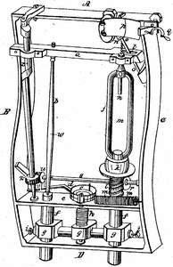
Fig. II. W. upright shaft. a.e. crank on the shaft. b. pinion. d. passing through the foot of the shaft. b. second sweep. f. stock holding the Drill. m. slot in the stock for the convenience of changing the Drill. n.n. Drill passing obliquely through the stock. i. screw to hold the drill firmly in the stock. q. apparatus to hold the axe during the process of drilling. m. Drill k. arm on the neck of the stationary screw. x. place of the dog for the ratch wheel showing where the spiral spring is attached to it. x. screw that holds the drill.
Explanation of the Drawing—
Fig. I. A.B.C.D. Frame of the machine, e. shaft f.f. steps the right hand one supporting the drill and stock, and the left hand one supporting the sweep. g.g.g. bar of iron through which the strip passes. h. stationary screw. i. i. levers answering as keys to confine the steps f.f. in the bar g.g.g. j. stock holding the drill. k. Drum or wheel for the band
Page 5.
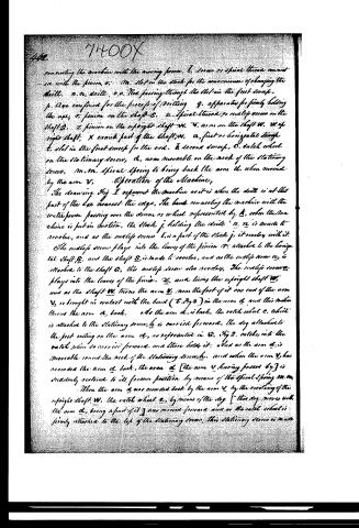
connecting the machine with the moving power, I, screw or spiral thread connected with the pinion, o. M, slot in the stock for the convenience of changing the drills. n, n, drills, o, o, Rod passing through the slot in the first sweep. p, Axe confined for the process of drilling. q, apparatus for firmly holding the axe, r, pinion on the shaft S. u, Spiral thread, so called screw on the shaft S. z, pinion on the upright shaft W. V, arm on the shaft W. W, upright shaft. x, crank part of the shaft W. a, first or horizontal sweep. t, slot in the first sweep for the rod. b, second sweep. c, ratchet wheel on the stationary screw, d, arm movable on the neck of the stationary screw, m, m, spiral spring to bring back the arm d, when moved by the arm V.
Operation of the Machine,
The drawing Fig. 1 represents the machine as it is when the drill is at that part of the axe nearest the edge. The band connecting the machine with the water power passing over the drum or wheel represented by k, when the machine is put in motion, the block j, holding the drills n, n is made to revolve, and as the endless screw t, is a part of the block j, it revolves with it. The endless screw plays into the leaves of the pinion r, attached to the horizontal shaft S, and the shaft S, is made to revolve, and as the endless screw u, is attached to the shaft S, this endless screw also revolves. The endless screw plays into the leaves of the pinion z, and turns the upright shaft W, and as the shaft W, turns the arm V, near the foot of it one end of the arm V, is brought in contact with the bend (t Fig 2) in the arm d, and this motion throws the arm d, back. As the arm d, is back, the ratchet wheel c, which is attached to the stationary screw, h, is carried forward, the dog attached to the foot resting on the arm d, as represented in S. Fig 2, catches into the ratchet when so carried forward, and thus holds it. And as the arm d, is movable round the neck of the stationary screw, h, and when the arm V, has moved the arm d, back, the arm d, [the arm V having passed by] is suddenly restored to its former position by means of the spiral spring m, m. When the arm d, was moved back by the arm V, by the revolving of the upright shaft W, the ratchet wheel c, by means of the dog [this dog moves with the arm d, being a part of it] was carried forward and as the ratchet wheel is firmly attached to the top of the stationary screw, this stationary screw is made
Page 6.
To perform a part of a revolution, and as there is a thread or screw cut in the bar g.g.g. at the middle g, and as this stationary screw rests with its end upon the bottom of the frame, and as the slips f.f. are moveable up and down through the slot e and bottom of the frame, the bar g.g.g. & therefore the slips f.f. become confined to the bar by means of the screws i.i. over all raised upwards. And as the stock j rests upon the top of the right-hand slip f, the stock j was raised upward at the same time, and consequently the drill n.n. and the second sweep b, which rests upon the top of the left-hand slip f, was raised upward in the same manner, and this constitutes the feed or the motion of the drill into the eye of the axe.
I will now describe the manner by which the drill is made to traverse and cut over all parts of the eye equally. The eye of the axe is made tapering or conical both ways to the centre. This is its usual shape and is so formed for the convenience of holding or wedging in the handle or handle, only machine is constructed so to give this form to the eye.
The lower end of the crank x, on the shaft w, describes when it revolves a larger circle than the top or upper end of it; during the sweep of drilling half the eye of an axe, the first sweep a, which is placed horizontally, slips or is raised upwards on the crank x, by means of stationary screw b a distance equal to half the width of the axe.
I now suppose the machine to be in the same position as when the first operation of it began, because the motion now to be described was performed at the same time with that, as the shaft s revolves, the upright shaft w, begins to revolve in like manner, and the first sweep a being attached to the crank x on the shaft w, as the shaft w turns the stock j, and consequently the drill n.n. is carried from that part of the eye next to the edge of the axe, towards the head or back of the axe, and the drill traverses the whole width of the eye in half of a revolution of the shaft w, and at each successive semirevolution of the shaft w, the first sweep a, by means of the stationary screw b being raised upwards, a smaller circle is described by that particular part of the crank x occupied by the first sweep a, and consequently a smaller circle is formed over by the drill, and in this way as the first sweep a rises on the crank x, the eye of the axe is diminished in thickness or made tapering.
Page 7.
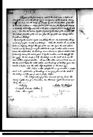
The eye of the first sweep a, next to the drill or r, is kept in its place by the rod o o in the slot t, and in consequence of the sweep a turning on the rod o o, and the sweep a being raised by each revolution of the shaft, as near the inclined or oblique position of the rod o o, the height of the sweep a is constantly diminishing, and with it the space or surface passed over by the drill or r. And these two actions together produced by the shape of the crank, and the inclined position of the rod o o, from the eye of the axe tapering both in breadth and thickness.
By making the crank r, regular and placing the rod o o perpendicular, the eye would be of uniform breadth and thickness. When the machine has carried the drill one half way through the eye of the axe, the dog on the ratch wheel is raised, and by means of a weight attached to a rope or chain which is wound round the ratch wheel, the stationary screw is turned in opposite direction to that produced by means of the motion given it by the machine, and the stops f f, the bar g g g, the two sweeps a and b, the stock j and the drill or r are let down to their original position. The axe is then taken out and turned over, and the dog released upon the ratch wheel, and the process of drilling again commenced as before, and the other half completed in the same way.
All I claim in this specification as my invention or improvement is the application of machinery in carrying forward the drill to the drilling out the eyes of axes in proper shape.
In witness whereof I have hereunto set my hand this twenty eighth day of November, one thousand eight hundred and thirty two.
Witness
Christopher Columbus Ballou
S. W. Harrington
Milton D. Whipple
2960
drawing $5.
Published accounts: journal notice
Notice in the monthly list of patents, with remarks
Journal of the Franklin Institute, new ser., vol. 12 (1833), p. 34 · View the page
39. For a machine for Drilling the Eyes of Axes; Milton Dexter Whipple, Douglass, Worcester county, Massachusetts, January 31.
Remarks. This appears to be a well arranged machine, the object of which is the making the eyes of axes perfectly true, and of a size, by means of a drilling or boring apparatus of a peculiar construction. The patent is taken for the machine as described, the idea of boring, or drilling the eyes not being considered as new. The patent taken by Benjamin Smith, on the second of November last, is, in part, for an apparatus for drilling the eyes of axes, but the two do not resemble each other. As the present machine is complex, and dependent altogether upon its peculiar construction, it would require an engraving for its clear explanation.
DATAMP: illustration
Illustrations from DATAMP

DATAMP (Directory of American Tool and Machinery Patents), via the Internet Archive · Archived DATAMP page
About this record
- Patentee
- DATAMP
- Date
- the Name and Date index of patents, DATAMP, USPTO records
- Invention
- DATAMP
- Listed in
- the Name and Date index of patents, DATAMP, USPTO records, Jim Shaw's X-patent list, the Journal of the Franklin Institute, Burke's List of Patents (1847)
- Burke's 1847 Patent Office list gives the same patent.