

Drawings and documents
National Archives restored drawings: drawing
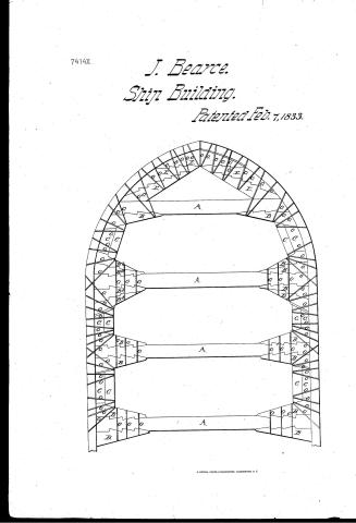
John Bearce's Patent Drawing for a Lock Dove Tail Key Purchace


National Archives, Restored Patent Drawings (Record Group 241) · Full-size scan at the National Archives · Catalog record
Show the text on the drawing Hide (78 words)
Words on the drawing as machine-read by the National Archives; not checked. Useful mainly for searching.
Sheet 1. CLASSIFICATION / DIV ISION. / TW4X John Delearces / LOCK DOVE TAIL KEY PURCHACE. / In bus lding searin / Zy / E. / Bb / Bb / Bb / Bb / Side Ship / Side ofthe Ship Side Skip
Sheet 2. 4 SHIPS / 1. CONSTRUCT / 137 Builo / Y2 / J. Bearce / Lock Dove Tail Key Purchace / CLASSIFICATION / Patented Feb. 7th1833 / 7414.+ / DIVISION / collect a Lock Nove-tail key. Purchase / Bo / Larrys Is eyezy Summrg A so Summary / BE
USPTO scan
The patent as scanned by the USPTO
-
 Page 1
-
 Page 2
-
 Page 3
-
 Page 4
-
 Page 5


U.S. Patent and Trademark Office · Google Patents
Show the transcription Hide (1,643 words)
Machine transcription (LightOnOCR) of the pages as scanned by the USPTO, most of them the handwritten copies made when the records were restored after the 1836 fire. Not checked; it can misread handwriting, so compare it with the scan.
Page 1.
7414X.
J. Bearce.
Ship Building.
Patented Feb. 7, 1833.
<!-- Image: A technical drawing of a ship's hull structure, labeled with letters A, B, C, E, and O, showing internal framing and planking. -->
Page 2.
John Pearce Bristol Maine
Letters Patent
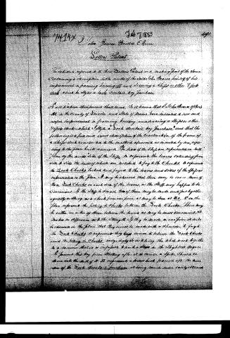
The schedule referred to in these Letters Patent and making part of the same containing a description with the words of the said John Pearce himself of his improvement in framing bracing and securing a ships or other Vessel deck which he styles a lock deck or lock brace.
It will be known this patent shall issue. It is known that I John Pearce of Bristol in the County of Lincoln and State of Maine have invented a new and useful improvement in framing bracing and securing a ships or other Vessel deck which I style a lock deck or lock brace and that the following is a full and exact description of the construction of the braces of a ship's deck conformable to the method of service as invented by me, referring to the plan hereto annexed. The sides of the ship are represented on said plan by the under side of the ship. A represents the beams extending from side to side the ends of which are bolted or fixed to the cheeks. B represents the lock cheeks bolted and fixed to the beams and sides of the ship as represented in the plan. It may be observed that there may be one or more of these lock cheeks on each side of the beams, as the ship may happen to be convenient. If the ship be small two of these may be made and fast together equally as strong as a check from one piece as may be seen at B. C in the plan represents the filling or checks between the lock cheeks. There may be either one or two of these between the beams as may be most convenient. It makes no difference as to the strength if they be made in one piece as seen between in the plan that they must be made with a shoulder to fasten the lock cheeks. D represents they keep them in between the lock cheeks and the filling in checks, not only by its holding the whole work together but a manner that it is impossible to work a shiver in the slightest degree. It prevents the boy from starting after it is driven a spike there to be driven into the end of it. E represents a heart hook framed after the manner of the lock deck or lock brace at being much more easily taken.
Page 3.
as almost any timber will make me, and is also much better and stronger than a common breast lock.
On opposite the bolts which are fastened are driven in square braces & braces and in the middle on opposite sides plates extending across the braces. These bolts must not be more than two inches the size of bolts required for teak panels with knees in the usual way. The advantage of securing the deck of a ship with straight teak in the manner of the Sack check is that key fastens instead of knees are used. First the timber is much less expensive and more easily obtained. Secondly, it is very much stronger and cannot work but must continue firm as long as the wood remains sound. To frame a deck in this manner, take a piece of timber say four feet long, fourteen inches wide and nine inches thick (according to the size of the ship) and split it obliquely three times. Then put the straight grain side on to the end of the beam with three locks in each strip, lay it on the beam (into which locks have been cut in the same way) before the beam is put into the space. The wood then fastens to the beam, and a Sack Check. One of them must be on each side of the beam but both ends. It will be readily perceived that they are much cheaper and more easily obtained than knees. When bolted as on the plan must be much stronger. Between the check on one beam and that on the other, put in what is called a fitting in check. This may either be one or two pieces, if in two pieces the inner one may be of pine or any other soft wood lying equally as good as oak. The outer one should be of hard teak and say nine inches thick, and the inner one eight inches thick. Make a keyhole cut into the Sack Check. A space should be left between one end of the fitting in check and the Sack Check for a key, which should be made with half an inch depth.
Having fastened the fitting in check as before mentioned, proceed to bolt them with four bolts extending from the outside of the ship (square and round and being inserted upon thick plates of iron extending across and let into the fitting in check) so that they cannot slip. Then drive the keys through and can be driven so as to let every joint board & wood and secure the deck.
Page 4.
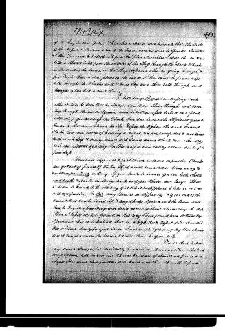
of the key with a spike. When this is done it will be seen that the side of the Yoke is drawn close to the beam and cannot be spread. Start at the fore end & bolt the Ship at the plan described. Then the in & out bolts a throat bolt from the outside of the Ship through the Dock Cheeks in the end of the beams so that they keep each other in going through a fore Dock then in iron plates on the inside. Then drive the fore and aft bolts through the Cheeks and beams. Lay the in & three bolts through and through & fore lock & nut them.
In bolt long they drive a coping cock.
This it will be seen that the Strain can draw them through and coming through the inside Splice, and rivetted or fore locked on a plate extending quite across the Cheek there can be not the slightest give to the work. The more drawn to the Yoke the tighter the work draws. In the common mode of bracing a Yoke we are compelled to work hard with much slip & many times with small arms which can hardly be fastened without splitting. In this way we can easily obtain timber for from 30 p.
There are difficulties to be overcome and are expensive. Cheeks are got out of pieces of timber which would be wasted or thrown away & cost comparatively nothing. If you timber to strake you can lock Cheek on Cheek & make as strong work as if you timber more large. When a beam is braced in this way if it be not difficult to take it out as well as expensive. In this way there is no difficulty & if you make the beam so it can be taken off. Many Cheeks Spliced on to the beam and have been kept up as strong and solid as new without disturbing the deck. When a Yoke deck is framed in this way there found from actual experiment that it is as solid that in a high deck Yoke if the timbers are without doubt few feet heavier than would be necessary by placing any strakes higher or so brought under the beams to raise them half an inch.
This method is not by much stronger, but decidedly handiomer than any other. The work being Splice with no corners which are known to be of almost all forms and shapes. This work stronger than ever known—in their strength depends
Page 5.
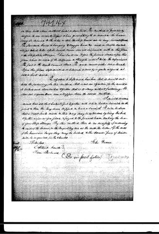
on their bolts alone without locks or dovetails. The method is presently applied to an armed Vessel where great strength is wanted, the beams being so secured to the sides as that the ship could not in any event have the stanchions knees & hanging & dagger knees be used in double decked ships which take up so much room are all dispensed with in this plan & the ship still stronger. I have built on Vessel the present frame upon this plan where no idea of the difference in strength existed but the experiment the fact is the work cannot stand. The work must either rot or break. Upon this plan I have proved it is believed is nearly or quite as good as oak or holly oak.
The objection to Soffwood has been that it would not hold the fastening. In this method, that is not an objection to the screws to be locked and electrofied together that it is strong without fastening. It does not require more iron or copper than the usual method.
I would recommend that all the locks be put together with white lead or tarnish in the joints & then the key done & dipped in lead or tarnish. I will be sure that a breast lock made in this way may be strengthened by being locked together as far as you please & joined to the forward beam making the beam of your ship stronger. By this method there is no necessity of reducing the ends of the beams for the longer they are as the more the better. If the ends of the beams are large they may be locked to the frames. Space of timber will be required for the cheeks.
John Pearce
Witnesses:
Albert Smith
John Berland
(On an post folio)
Published accounts: journal notice
Notice in the monthly list of patents, with remarks
Journal of the Franklin Institute, new ser., vol. 12 (1833), p. 88 · View the page
12. For a mode of Framing, kneeing, and securing a Ship's or other Vessel's Deck; John Bearce, Bristol, Lincoln county, Maine, February 7.
Remarks. The mode of framing, and securing together the timbers of a vessel's deck adopted by the patentee, he denominates a lock, dovetail, key purchase. Beams extend across from side to side of the ship in the usual way, but instead of securing them to the sides by knees, lock chocks are employed for that purpose; these lock chocks are notched, by dovetail notches, into the beams, in the manner in which trussed girders are sometimes notched; or rather in the manner of joining timbers to bear a longitudinal strain. Filling-in chocks, in one or two thicknesses, are fastened to the vessel's side, between the beams, and are made with a shoulder to fay to the lock chocks. Keys are driven in, wedgingly, between the lock chocks and filling-in chocks, to make all firm. The bows are also strengthened by a breast hook, made up of timbers united in the manner of the lock, dovetail, purchase, and bolted together.
About this record
- Patentee
- DATAMP
- Date
- DATAMP, USPTO records
- Invention
- DATAMP
- Listed in
- the Name and Date index of patents, DATAMP, USPTO records, Jim Shaw's X-patent list, the Journal of the Franklin Institute, Burke's List of Patents (1847)
- The sources give different dates; the date shown is the one most of them agree on.
- The Franklin Institute's journal confirms the date shown.
- Burke's 1847 Patent Office list gives the same patent.