

Drawings and documents
National Archives restored drawings: drawing
Sereno Newton's Patent Drawing for a Printing Press

National Archives, Restored Patent Drawings (Record Group 241) · Full-size scan at the National Archives · Catalog record
Show the text on the drawing Hide (55 words)
Words on the drawing as machine-read by the National Archives; not checked. Useful mainly for searching.
SERENO NEWTON'S / 101. PRINTING, / CLASSIFICATION / PRINTING PRESS / 7443 X / DIVISION. / FIG.1. / C. / ET / SOLD / Patented 26th Feb y 1833. / TO / Mathew Smith, & Richard M. Hoe; / 8th Oct... 1835. / # 7443x / QP / Al / of / III / FIG 2. / FIG.3. 1. / 00 / BARRAR C / (0) / one / and / DI / hang
USPTO scan
The patent as scanned by the USPTO
-
 Page 1
-
 Page 2
-
 Page 3
-
 Page 4
-
 Page 5
-
 Page 6
-
 Page 7
-
 Page 8


U.S. Patent and Trademark Office · Google Patents
Show the transcription Hide (2,124 words)
Machine transcription (LightOnOCR) of the pages as scanned by the USPTO, most of them the handwritten copies made when the records were restored after the 1836 fire. Not checked; it can misread handwriting, so compare it with the scan.
Page 1.
7443X
S. Newton. Sheet 1 of 3 Sheets.
Printing Press.
Patented Feb. 26, 1833.
No.
Fig. 1.
Page 2.
7443y
S. Newton.
Printing Press.
Patented Feb. 26, 1833.
Sheet 2 of 2 Sheets.
No.
FIG. 2.
Page 3.
7443y
S. Newton. Sheets & Sheets
Printing Press.
Patented Feb. 20, 1833.
Fig. 3
Fig. 4
Fig. 5
Fig. 6
Page 4.
7443X 2/26/1883
Feb. 26, 1883
Seno & Morton of New York City
Letters Patent
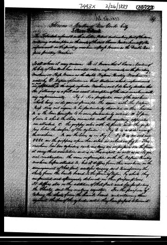
The undersigned referred to in the letter Patent and making part of the same, containing a description in the words of the said Seno Morton himself of his improvement in the printing machine of the type known as the Double Napier's Printing Machine.
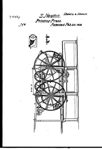
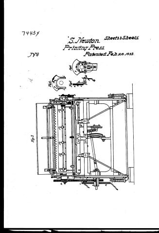
To all whom it may concern: Be it known that I, Seno Morton of the City of New York have invented certain improvements in the printing Machine or Press known as the double Napier's Printing Machine, invented by D. Napier of London in Great Britain, which improvements are applicable to the single cylinder Machine, and I do hereby declare that the following is a full and exact description of the said machine with my improvements. Fig 1. Is a perspective view of the machine which being in its general principle the same with the Napier Press does not require to be particularly described in this, however A is the lever hereafter to be more particularly noticed. B of piece of iron to which the slides connected with the regulating apparatus are attached. C. the gripper wheel with its pivots and the grippers below the surface of the cylinder. Fig 2. is a side view of the machine. D are the levers as in Fig 1. Fig 3 is an end view of the grippers upon their arbor as noticed in fig 1. This machine has two cylinders each making an impression on the form at every third revolution and is in this respect, as well as in its general construction, the same in principle with the Napier Printing machine before alluded to, but it differs from this machine in the arrangement of that part used for raising and transferring the sheets from the blank board to the form of type, by which they are printed and afterwards delivered in their proper places. It differs also in the addition of that part used for perfecting the sheets, and thus making register. For the purpose of taking the sheets from the blank board, and returning them against the face of the cylinder until they have passed between it
Page 5.
and the type and afterwards, seizing and delivering them in their proper places. I attach to each cylinder the same kind of apparatus, more or less, as that used by the said Napier, in his well known single cylinder Printing Machine for that purpose. That is to say, an iron rod or bar which I have called the gripper arbor. The grippers being so fitted thereon that they may be secured by tightening screws on my part required. Near one end of the gripper arbor there is a pinion of about one inch and a quarter in diameter, fixed permanently and this takes into a wheel which I call the gripper wheel, of about four inches in diameter having on about one fifth of its circumference teeth which correspond with those on the pinion.
A roller of steel or glass called the check roller, made of the same thickness as the gripper wheel is forced into its face by a steel spring and is thus made to fall into cavities formed on the periphery of the wheel at suitable distances; thus serving the purpose of stopping and retaining the grippers in their proper places. Near the periphery of the above wheel and and parallel to its axis a pin with a friction roller on its end projecting one inch or more beyond the end of the cylinder, this in the single cylinder machine at every revolution of the cylinder comes in contact with segments or pieces of iron of suitable form fastened permanently near the end of the cylinder, and thus by acting on the above named friction rollers attached to the gripper wheel, causes the grippers to close and open at every revolution of the cylinder.
But in order to adapt these to my machine, a concavity is formed on one side of the cylinder of sufficient depth to admit the gripper arbor and its appendages to be sunk below the face of the cylinder, so as to pass clear of the type on the bed as the form passes under the cylinder, and also to allow the grippers with their arbor, to make nearly half a revolution back from the position in which they hold the sheet to the cylinder. The concavity terminates at a little distance from one end of the cylinder so as to leave a space to receive the part of one end of the gripper arbor. The other end, on which the pin-
Page 6.
7443x
171.
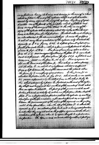
iron is fastened having its bearing and turning in the arm of a wheel which is fitted to the end of the cylinder shaft and which is also secured by screws against the end of the cylinder. They being of equal diameter. One of the pivots of the gripper wheel is fitted to and turns in one of the arms of this wheel & the other in one of the arms of the cylinder which standing about two inches within its and leaves a suitable space for that purpose. The check roller and the spring are also attached to the chronometer wheel. To cause the grippers to act at every third revolution of the cylinder only I attach the segments a b & c figure 4 & 5. to a plate of iron P of about one fourth of an inch thick — which is permanently fastened to the piece of iron X figs 5 & 6. This piece of iron turns upon a bolt or pins at i i and consequently allowing the plate P to move back and forward. The piece of iron p, figs 5 & 6. is fitted to and turns on a joint in the piece X, at c c. There is a groove or slot in the lower end of the piece p, thro which a screw passes into the slide S, in which it is tightened whilst a sufficient space is left between the head of the screw and the slide to allow the piece p to move freely up and down. To this piece p is attached the friction roller d figs 5 & 6. which works in an eccentric groove represented by the dotted lines in the wheel R fig 6. This wheel is driven by a pinion h, fastened on the end of the cylinder shaft and having on it but one third of the number of teeth which there are upon the wheel R. The part y of the groove must be such portion of a circle as will, by its action on the friction roller keep the plate P in a perpendicular position whilst the cylinder is making about five sixths of a revolution, or for such a period as is required between the commencement of the action of the segments on the grippers until it has passed them, when the top of the plate P, to which the segment a b & c are attached, falls back into a horizontal position in order that they may not act on the grippers again until the third revolution of the cylinder when it is again brought to a perpendicular position. The tapes or cords are conducted by rollers & pulleys.
Page 7.
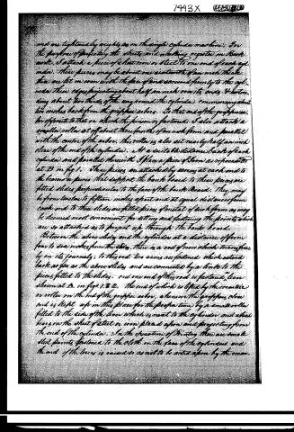
and are tightened by weights as in the simple cylinder machine. For the purpose of perfecting the sheets and making registers in Book work, I attach a piece of sheet iron or steel to one end of each cylinder. These pieces may be about one sixteenth of an inch thick, they are let in even with the face of the end and secured firmly to the cylinder, their edges projecting about half an inch over its ends. Extending about two thirds of the way round the cylinder, commonery about two inches back from the griffon arbor. To that end of the griffon arbor opposite to that on which the pinion is fastened, I also attach a smaller roller set off about three fourths of an inch from and parallel with the centre of the arbor. This roller is also set nearly half an inch clear of the end of the cylinder. At a suitable distance back of each cylinder and parallel therewith I place a piece of board as represented at B in fig 1. These pieces are attached by screws at each end to the boards or pieces that support the bank board to these pieces are fitted slides perpendicular to the face of the bank board. They may be from ten to fifteen inches apart and at equal distances from each end to these slides are fitted pieces of metal of such form as may be deemed most convenient for setting and fastening the points which are so attached as to project up through the bank board. Between the above slides and the cylinder at a distance of from four to six inches from the slides, there is a rod of iron which turns freely on its journals; to this rod two arms are fastened which extend back as far as the above slides and are connected by a link to the pieces fitted to the slides. One end of this rod is fastened, here shown at D in figs 1 & 2, the end of which is lifted by the eccentric or roller on the end of the griffon arbor, whenever the griffon arbor and is kept up in this place for the proper time by a small roller fitted to the side of the lever which is next to the cylinder and which bears on the sheet of steel or iron placed upon and projecting from the end of the cylinder. In the operation of printing there are small steel points fastened to the cloth on the face of the cylinder and the end of the lever is raised so as not to be acted upon by the eccentric.
Page 8.
7443X
77
the one on the end of the gripper arms. The sheet of paper is laid on the lower board with the edge a little over the centre of the cylinder and at the proper time the grippers catch the sheet and convey it between the top and the cylinder. The top pressing the points thru the paper which is carried between the cylinder and form and points on inside. When the second side is to be printed the lever is let down and the sheet put on the points projecting through the board which made let us to correspond with the holes made in the sheets by the points on the face of the cylinder and at the moment the grippers catch the sheet the points are withdrawn from it by the operation of the eccentric fixed upon the end of the gripper arms which acting on the before described lever raises the end of it until the roller attached to the side of it bears on the projecting sheet iron or steel on the end of the cylinder. When the bearing roller comes off from the end of the sheet metal the lever is brought down by the action of a spiral spring attached to the end on which the lever is fixed. During the next two revolutions of the cylinder the projecting sheet metal on the end of the cylinder bears on the roller on the side of the lever.
What I claim as new and for which I ask a Patent, is the machinery herein described is the application of the above described grippers to a printing machine, the cylinders of which make three revolutions to one impression, whether the apparatus by which they are acted upon is constructed exactly in the manner described, or in any other operating upon the same principle and producing the similar result.
I also claim the particular mode herein described of withdrawing the apparatus which acts upon the grippers, not only by making three but also to those making only two revolutions to each impression. I also claim the application of the eccentric attached to the end of the gripper arms for the purpose of withdrawing the points from the sheets, as applicable to the single as well as the double cylinder Printing Machine.
Witnesses
Wm. H. Bullfinch Jr.
Patentee
Patentee (Signature)
2093
Published accounts: journal notice
Notice in the monthly list of patents, with remarks
Journal of the Franklin Institute, new ser., vol. 12 (1833), p. 102 · View the page
41. For an improved Double Cylinder Register Printing Press; Sereno Newton, city of New York, February 26.
Remarks. Among the most celebrated of the printing presses which have been invented in England, and which have facilitated the business of printing to an extent which is truly astonishing, those of Mr. Napier, and of Cowper, and Applegarth, stand conspicuous. The improvement for which Mr. Newton has obtained the present patent, is for a modification and combination of certain parts of each of these presses. In England this could not have been done, the separate parts belonging to the respective patentees; the combination made by Mr. Newton, if it had been thought of there, would have required the concurrent consent of each of the parties. What is now claimed as new is the "combining that part of the Napier printing machine which constitutes the bed, and its appendages, with the cylinders, and such other parts of the superstructure of the Cowper and Applegarth's printing press as are employed in the receiving and conveying of the sheets."
About this record
- Patentee
- DATAMP
- Date
- DATAMP, USPTO records, Burke's List of Patents (1847)
- Invention
- DATAMP
- Listed in
- the Name and Date index of patents, DATAMP, USPTO records, Jim Shaw's X-patent list, the Journal of the Franklin Institute, Burke's List of Patents (1847)
- The sources give different dates; the date shown is the one most of them agree on.
- The Franklin Institute's journal confirms the date shown.
- Burke's 1847 Patent Office list gives the same patent.