

Drawings and documents
National Archives restored drawings: drawing
Solomon Deming's Patent Drawing for a Wind Mill

National Archives, Restored Patent Drawings (Record Group 241) · Full-size scan at the National Archives · Catalog record
Show the text on the drawing Hide (104 words)
Words on the drawing as machine-read by the National Archives; not checked. Useful mainly for searching.
MATICS. / Wind Wheels. / CLASSIFICATION / Horizontal. / 7470-x / Blomon Timing / Wind Mill / DIVISION. / Patented S Marce Marc 1830 / Fif.1. / ap / Fifed, / II / Fid,4, References, Section vertical, / Fid.2, perspective. / A. mill, B, upper platform. C.lower platform. / D,shaft. E up ht parts, Encrops pieces. / G, G'eircula heads. Hwmos, I. outer posts. / J. shutters, II. cord for opening shutters. I cord for / closing detter M cog wheel? / Pathut Office Dee 9. 1841. / Made under the direction of the Comminious of Patents / in conformity with Out of bongrep 3 March L sumart 1837, / Commissioner of Paturts,
USPTO scan
The patent as scanned by the USPTO
-
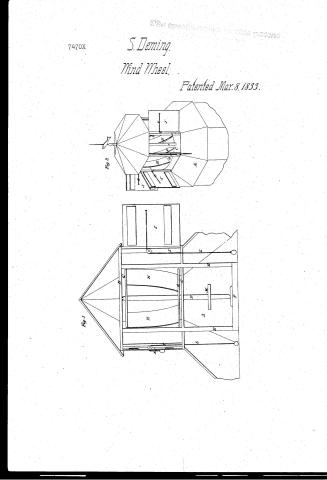 Page 1
-
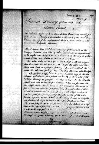 Page 2
-
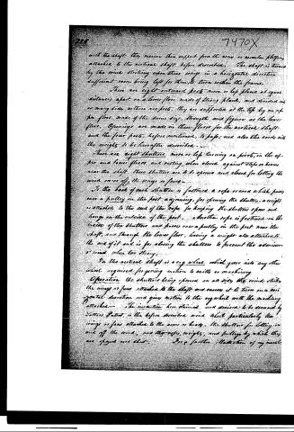 Page 3
-
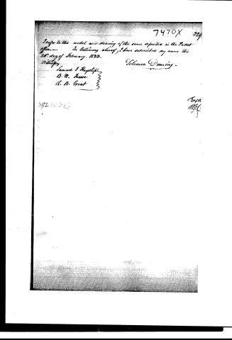 Page 4


U.S. Patent and Trademark Office · Google Patents
Show the transcription Hide (803 words)
Machine transcription (LightOnOCR) of the pages as scanned by the USPTO, most of them the handwritten copies made when the records were restored after the 1836 fire. Not checked; it can misread handwriting, so compare it with the scan.
Page 1.
7470X
S. Deming,
Wind Wheel,
Patented Mar. 8, 1833.

Page 2.
Mar 8 1833
Solomon Denning of Brunswick, Ohio
Letters Patent.
The schedule referred to in these Letters Patent and making part of the same, containing a description in the words of the said Solomon Denning himself of his improvement being a wind wheel or mill, turning in a horizontal direction.
Be it known that Solomon Denning of Brunswick in the County of Medina, and State of Ohio, have made an improvement in the useful arts, being a wind wheel or mill turning in a horizontal plane and which is assembled as follows.
This wind wheel consists of a vertical shaft with the wings or fans to receive the wind to turn the shaft. The upper and lower floors and posts or uprights forming a frame to support the works; the shutter, pulleys, &c. for admitting the wind upon the wings.
The vertical shaft is made of any suitable size for the mill intended to be built. It is placed vertically in the centre of the building, turning on guigeons or steps or boxes. On the top of the shaft, and also at the proper distance below are frames into the shaft twelve arms more or less to receive the wings or fans. Or two circular platforms may be constructed of thick plank to answer the same purpose. The shaft receives its support from four posts passing through the centre of the mills framed together at the bottom by two strong beams, or cross pieces and fastened by keys or bolts on the upper platform or floor.
The upper guigeon of the shaft turns in a box placed in a cross piece in the upper platform, and the lower guigeon turns in a box or step on the cross piece below.
There are about twelve wings or fans more or less placed round the shaft at equal distances apart, at an angle of about 45 degrees.
Drawing
Page 3.
with the shaft; they receive their support from the arms or circular plates, attached to the vertical shaft, before described. The shaft is turned by the wind striking upon these wings in a horizontal direction sufficient room being left for them to turn within the frame.
There are eight outward posts more or less placed at equal distances apart, on a lower floor made of strong planks, and divided into as many sides as there are posts. They are supported at the top by an upper floor made of the same size, strength, and figure as the lower floor. Openings are made in these floors for the vertical shaft and the four posts, before mentioned, to pass; and also the cords with the weights to be hereafter described.
There are eight shutters more or less turning on pivots, in the upper and lower floors and resting, when closed, against stops or beams near the shaft. These shutters are to be opened and closed for letting the wind on or off the wings or fans.
To the back of each shutter is fastened a rope or cord which passes over a pulley in the post adjoining, for opening the shutter; a weight is attached to the end of the rope for keeping the shutter open and hangs on the outside of the post. Another rope is fastened on the inside of the shutter and passes over a pulley in the post near the shaft, and through the lower floor, having a weight also attached to its end of it and is for closing the shutters to prevent the admission of wind when too strong.
On the vertical shaft is a cog wheel which gears into any other wheel required for giving motion to mills or machinery.
Operation: the shutters being opened on all sides, the wind strikes the wings or fans attached to the shaft and causes it to turn in a horizontal direction and gives motion to the cog wheel with the machinery attached. The invention here claimed and desired to be secured by Letters Patent, is the before described wind wheel particularly the wings or fans attached to the arms or beams, the shutters for letting on and off the wind; and the ropes, weights, and pulleys by which they are opened and closed.
For a farther illustration of my invention
Page 4.
I refer to the model and drawing of the same deposited in the Patent Office. In testimony whereof, I have subscribed my name this 20th day of February, 1833.
Witness:
Samuel J. Haypliff
B. W. Furse
R. B. Grant
Solomon Denning
7470X 329
Expa
M.G.C.
Published accounts: journal notice
Notice in the monthly list of patents, with remarks
Journal of the Franklin Institute, new ser., vol. 12 (1833), p. 174 · View the page
16. For a Horizontal Wind Mill; Solomon Deming, Brunswick, Madeira county, Ohio, March 8.
Remarks. There is some obscurity about the description of this contrivance, but still, through the palpable obscure, we can perceive enough to convince us that the difficulties which have hitherto attended the use of horizontal wind mills, will not be removed by the present modification of them. A vertical shaft is to be erected, and to arms, or heads which it carries, there are to be attached about twelve vertical wings, upon which the wind is to operate. The wings are to stand at an angle of about fourteen degrees with the shaft. This part is to be surrounded by frame work, sustaining eight, or any other suitable number of doors, hinged to vertical posts. These are to be opened or closed by cords and pulleys, to admit or arrest the wind, according to circumstances. The invention claimed is "the before described wind wheel, particularly the wings or fans attached to the arms, or heads, the shutters for letting on and off the wind; and the ropes, weights, and pulleys by which they are opened and shut."
About this record
- Patentee
- DATAMP
- Date
- the Name and Date index of patents, DATAMP, USPTO records
- Invention
- DATAMP
- Listed in
- the Name and Date index of patents, DATAMP, USPTO records, Jim Shaw's X-patent list, the Journal of the Franklin Institute, Burke's List of Patents (1847)
- Burke's 1847 Patent Office list gives the same patent.