

Drawings and documents
National Archives restored drawings: drawing
M. Mettee's Patent Drawing for a Pump

National Archives, Restored Patent Drawings (Record Group 241) · Full-size scan at the National Archives · Catalog record
Show the text on the drawing Hide (44 words)
Words on the drawing as machine-read by the National Archives; not checked. Useful mainly for searching.
CLASS 103. PUMPS / JMPS / CLASSIFICATION / Bagg / 225- / Elements, / Operating Devices / 7471X / M. METTEE S PUMP. / 7471X / Patented March 9th 18ir / 41 / 53 / 57 / 55 / 12 / male / female / ~v / 13 / пат / Screw / 161 / 42 / 19 / 31 / 40 / either male / or / female / serew / 46 / 36½ / 47 / 48
USPTO scan
The patent as scanned by the USPTO
-
 Page 1
-
 Page 2
-
 Page 3
-
 Page 4
-
 Page 5
-
 Page 6
-
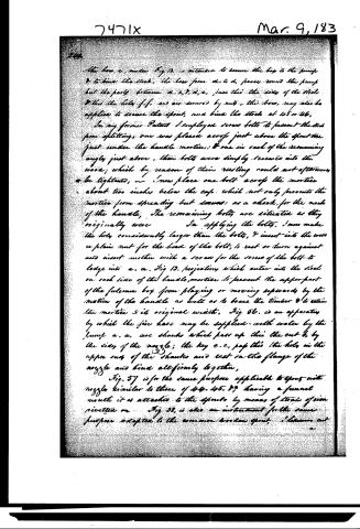 Page 7
-
 Page 8


U.S. Patent and Trademark Office · Google Patents
Show the transcription Hide (2,458 words)
Machine transcription (LightOnOCR) of the pages as scanned by the USPTO, most of them the handwritten copies made when the records were restored after the 1836 fire. Not checked; it can misread handwriting, so compare it with the scan.
Page 1.
7471X
M. Mettee,
Pump Brake,
Patented Mar. 9 1833.
Page 2.
7471x
Mar 9, 1833
Martin Mettee of Baltimore City of Maryland
Innu Patent.
The schedule referred to in these Letters Patent and making part of the same, containing a description in the words of the said Martin Mettee, himself of his improvement in Pumps.
To all to whom these presents shall come,
Be it known, That I, Martin Mettee of the City of Baltimore & State of Maryland, have invented a new and useful improvement in the Pump, & that the following is a full and exact description of the construction and operation of the said machine or improvement as invented by me.
Fig 1. is a piece in my former Patent (which bears date of the twentieth day of May, one thousand and eight hundred and thirty) representing a fulcrum box attached to the pump stock, in which box the handle rests & operates. a, b. are two plates which join at the line c, d, by the hinge at e, f. is a section of the handle g. is the end of the neck receiving h, which is a section of the spear with a key.
Fig 2. also of the former Patent is a section of the handle as f. & g. Fig. 1. with the pin a, — The neck and pin are welded together forming one solid piece: the pin having shoulder square at the right & the handle driven on
Fig 3. of former Patent, is a section of the upper end of the spear, bent at a right angle, and prepared to pass thru the eye, as at Fig 1. — Fig 4, 5. of former patent, are hollow friction rollers adapted to the ends of the pin
Fig 5. of former patent, is the inside view of the fulcrum box Fig 1. without the handle & neck.
Fig 6. is an improvement on Fig 1. the motion thru which the handle passes, being so altered as to have out the flange a, Fig 5. & to accept the left side of the handle at the pin to come
Page 3.
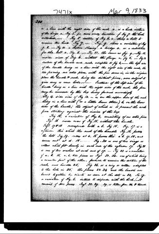
in a line with the right side of the neck, c, is a hook instead of the hinge a, Fig 1, for more ready dissection of Fig 7, the hook detached, — Fig 8, section of Fig 6, c, shows a bolt to receive the hook Fig 7, — Fig 9, shows a variation of Fig 7, c, — Fig 10 a section showing a bridge a, as a substitute for the bolt c, Fig 8, — Fig 11, the same as fig. 9, — Fig 12, inside view of Fig 6, without the flange a, fig 8, — Fig 13 section of the handle and neck, adapted to fig 6, — the left side of the handle being in a line with the right side of the neck, the two forming one entire piece, with the pin down in, in the original plan the handle & neck, being two distinct pieces, were subject to give way or come loose, — Instead of the left side of the handle being in a line with the right side of the neck, the form may be reversed by the boy being formed accordingly
Fig 14 side view of Fig 13, — a, on the upper side of the neck being in a line with (or a little lower than) b, or the lower side of the handle; the object of which is to prevent the neck from striking against the inside of the boy
Fig 15, a variation of Fig 6, consisting of one entire piece Fig 16 inside view of Fig 15, without the handle, Fig 17 & 18 corresponds with a b, Fig 15, Fig 17, is a cylinder thru which the neck of the handle Fig 18, passes, the bolt Fig 19, enters at c, 15 passes thru a b, 17, 18, and comes out at d, 15, — Fig 20 is one of two rings or rollers which fit loosely in each end of the cylinder 17, Fig 21 is one of two washers at each end of 17, — Fig 22, is a variation of a, b, 15, a, b, two pieces as Fig 23, 24, one of which being a counter part of the other, formed to receive the section of the neck, and handle 25, Fig 26, is a ring or roller adapted to the hole in 25, the pieces 23, 24 and the handle are bound together by rivets as seen at the dots in 22, Fig 27, a variation of Fig 6, instead to dispense with the hook, — It consists of two pieces Fig 28, 29, 29, is taken from 28, & turned
Page 4.
7471x
Mar 9, 1833
241.
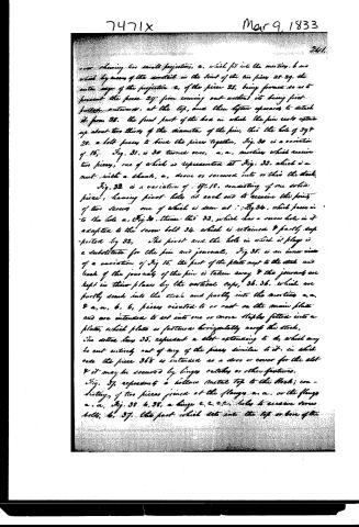
over showing two small projections, a, which fit into the mortises, b, and which by means of the armrest in the joint of the two pieces 28, 29, the outer edge of the projection c, of the piece 28, being formed so as to prevent the piece 29 from coming out without its being first pulled outwards, at the top, and then lifted upwards to detach it from 28. The front part of the box in which the pin rests extends up about two thirds of the diameter of the pin, this the hole of 348 28, a bolt passes to bind the pieces together, Fig. 30 is a variation of 15. Fig. 31 is 30 turned over, a, a, mortises which receive two pieces, one of which is represented at Fig. 32, which is a nut with a shaft, a, drove or screwed into or into the stock. Fig. 32 is a variation of Fig. 18, consisting of one solid piece, having pivot holes at each end to receive the points of two screws one of which is seen at Fig. 34, which passes in to the hole a, Fig. 30, thence the 32, which has a screw hole in it adapted to the screw bolt 34 which is retained & partly supported by 32. The pivot and the hole in which it plays is a substitute for the pin and journal. Fig. 35 is an inner view of a variation of Fig 15, the part of the plate next to the stock and back of the journals of the pin is taken away & the journals are kept in their places by the vertical caps, 36, 36, which are partly sunk into the stock and partly into the mortises a, a, & a, a, b, b, pieces riveted to or cast on the main plate and are intended to set into one or more staples fitted into a plate, which plate is fastened horizontally across the stock. The dotted line 35, represent a slot extending to d, which may be cut entirely out of any of the pieces similar to it, in which case the piece 365 is intended as a door or cover for the slot & it may be secured by hinges, catches or other fixtures. Fig. 37, represents a hollow metal top to the stock; consisting of two pieces joined at the flange a, a, or the flange a, a, Fig. 38, b, 38, a hinge c, c, c, c, holes to receive screw bolts, b, 37, the part which sets into the top or box of the
Page 5.
242.
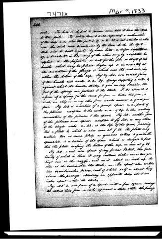
Stock. The hole in the part b, receives screw bolts to bind the stock to that part. The dotted lines d d, 38, represent a continuation of the side a, e, when the part b 37, or b, 38 is not attached in this case the stock will be embraced by the lines d. d. the top of stock will be bound together by screw bolts as before described. 37, a handle 38, as 38, any of the others may by adaptation be applied. a, the projection or seat for the pin or shaft of the handle which may be placed higher up or immediately at the connection of the flange in which case the neck will stay within the hollow of the cap. Fig. 39, 40, are varied forms of the handle and neck, c. c. 39. Spring supporting a roller b, against which the handle strikes, to give an easy reaction. the feet of the springs are fastened to the stock. F. 41 above 12, is a form of a spring for the same purpose — either this form, a circle, an ellipse or any other form would answer a good purpose. Fig. 42 is a section of a pump spear. a, a, parts of the piston adapted to the necks a. a. of 39. b, the working connection of the piston & the spear. Fig. 43, another form of the piston and spear, adapted to fig 40, or any other of the single necks a. 43. is the top of the spear, passing thru a plate b, which is also seen at f 38. the plate may contain two or more plain or grooved rollers to guide the spear. 42, is a section of the spear which is designed to pass thru the plate enclosing the hollow of the cap, as seen at g 38.
Fig. 44 a cast iron spout of my former Patent, the peculiarity of which is that it may contain either one or two grooves one in the nozzle, cast in it, about one inch up, the other at the back within the stock. The spout also contains two semicircular pieces, each of which half or about half closes the passage standing on opposite sides about two inches apart within the stock.
Fig. 45 a new form of a spout with a four square passage. the dotted lines from a. b. represent a slide within the passage.
Page 6.
7471x Mar 9, 1833
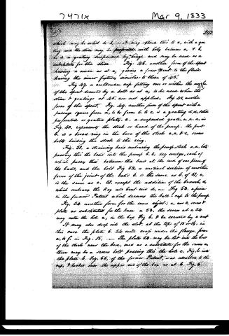
which may be solid to b, or it may extend thus to e, with a grating and the slide may be perforated, with holes between a, & b, a, is a grating suspended by hinge and may be used as a substitute for the slide. Fig. 48, another form of the spout having a curve as at a, giving a force spout to the fluid having the inner fixtures similar to those of 45.
Fig. 47, a cullender cap fitting over or within the mouth of the spout secured by a bolt as at a, is the need when the slide & gratings at 45, are not applied, Fig. 48, another form of the spout. Fig. 49, another form of the spout with a passage square from a, to b; from b, to c, is a grating d, d, slide perforated or grated plate, e, a suspended grate, a, a, a, in Fig. 50, represents the stock or head of the pump. The part b, is a broad ring in the bore of the stock e, e, & c, screw bolts binding the stock to the ring.
Fig. 51, a straining band embracing the pump stock a, a, bolt passing thru the band into the pump b, b, key wedges, each of which passes thru between the band at the end of one piece of the band, and the bolt Fig. 52, a vertical section of another form of the joint of the band b, is the same as b, of 51; e, is the same as e, 51, except the addition of the branch, d, which embraces the key and bent end d, in Fig. 53, a piece in the former Patent which secures the ball cap to the pump.
Fig. 54 another form for the same object; a, and b, screw & plate as substituted for the knee a 53, the screw at a 54 may enter the hole e, in the box Fig. b, & be secured by a nut. It may also drop into the slot, at the top of 15 or 16, in this case the plate b, 54 will crop under the flange, from e, to f, in Fig. 15. — The plate 54 may be let into the head of the stock near the bore, and as a substitute for the screw a, there may be a screw bolt passing thru the hole e, Fig. b into the plate b, Fig. 55, of the former Patent, was attached to the cap, & hooks over the upper end of the box as at b, Fig. 5.
Page 7.
The bow c, under Fig 12, is intended to secure the box to the pump & to bind the stock. The bow from a. to d, passes round the pump but the parts between a. e. f. d. e, pass this the side of the stock & this the hole f. f. and are secured by nuts. This bow, may also be applied to secure the spout, and bind the stock at 45 or 46.
In my former Patent I employed screw bolts to prevent the stock from splitting, one was placed across just above the spout and just under the handle mortice; & one in each of the remaining angles just above. These bolts were simply screwed into the wood; which by reason of their rusting could not afterwards be tightened. I now place one bolt across the mortice about two inches below the cap, which not only prevents the mortice from spreading but serves as a check for the neck of the handle. The remaining bolts are situated as they originally were.
In applying the bolts, I now make the hole considerably larger than the bolt, & insert into the wood a plain nut for the head of the bolt, to rest or turn against and insert another with a screw for the screw of the bolt to lodge into a. a. Fig 12, projections which enter into the stock on each side of the handle mortice to prevent the upper part of the fulcrum box from playing or moving upwards by the motion of the handle as well as to brace the timber & to retain the mortice to its original width. Fig 56, is an apparatus by which the fire hose may be supplied with water by the pump a. a. are shanks which pass up this the cut b, by the side of the nozzle; the key c. c. pass this the hole in the upper end of the shanks and rest on the flange of the nozzle and bind all firmly together.
Fig. 57 is for the same purpose applicable to spouts with nozzles similar to those of 44. 45. 49 having a funnel mouth it is attached to the spouts by means of straps of iron rivetted on. Fig 58, is also an instrument for the same purpose adapted to the common wooden spout. I hereunto set a
Page 8.
7471x
Mar 9, 1833
243
...in the nozzle. I also apply the common hyarant-plug or any other suitable one may be applied to any part of the pump for the purpose of supplying the Hose, a friction ring as 26. may also be applied to the eye of the mesh & joint of the spear. — After a careful examination I believe the improvements embodied in these drawings & descriptions to be my own invention, yet I wish it to be distinctly understood, that I claim nothing in either the principle, or the application which shall not prove to be my own & new,
Witnesses
J. B. Bailey
Edward Talbot
Martin Mettee
(Or in port folio)
2/52 nd
6x
Ch.
Published accounts: journal notice
Notice in the monthly list of patents, with remarks
Journal of the Franklin Institute, new ser., vol. 12 (1833), p. 175 · View the page
18. For an improvement in Pumps for Water; Martin Mettee, Baltimore, Maryland, March 9.
Remarks. On the 20th of May, 1830, Mr. Mettee obtained a patent for an improvement in pumps, with a view to prevent the introduction of stones and other injurio injurious substances into them, a notice of which patent will be found at p. 85, vol. vi. The present patent has the same object in view, and the patentee has manifestly taken great pains to accomplish it. The specification consists entirely of references to the drawings, which are fifty-six in number, showing his mode of forming and connecting the various parts appertaining to the handle and spout, to which his improvements are confined. At the close of his specification he says that after a careful examination, "I believe the improvements embraced in these drawings and descriptions to be of my own invention, yet I wish it to be distinctly understood, that I claim nothing in either the principle or the application which shall not prove to be my own, and new." Be it remembered, however, that to divide the chaff from the wheat, the old from the new, belongs not to the public, but to the patentee, and that the saving clause which he has introduced, as expressive of his good intentions, will not be as dust in the balance of the scales held in the hands of justice, or rather, perhaps, of law. We see no reason on the present occasion, to modify the remarks made on the former patent, but think them, generally speaking, perfectly applicable to the present. When we noticed Mr. Kreig's pump, (No. 11 in the Journal for last month,) we were impressed with the idea that this second patent to Mr. Mettee was of later date than that before us; this, however, is a mistake of no importance whatever.
About this record
- Patentee
- DATAMP
- Date
- the Name and Date index of patents, DATAMP, USPTO records
- Invention
- DATAMP
- Listed in
- the Name and Date index of patents, DATAMP, USPTO records, Jim Shaw's X-patent list, the Journal of the Franklin Institute