

Drawings and documents
National Archives restored drawings: drawing
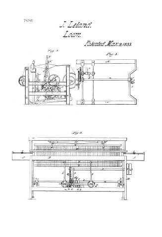
John Leland's Patent Drawing for a Broad Power Loom


National Archives, Restored Patent Drawings (Record Group 241) · Full-size scan at the National Archives · Catalog record
Show the text on the drawing Hide (71 words)
Words on the drawing as machine-read by the National Archives; not checked. Useful mainly for searching.
Sheet 1. JOHN LELAND'S / CLASSIFICATION / BROAD POWERLOOM. / 7.474X / Patented 9th March 1833. / DIVISION. / J. / FIG. 2. / V. / q. / B. / b. / b. / FIG.1. / FIG 3. / e.e / f. / 9.9. / 0. / S. / k. / olf / k. / d.d
Sheet 2. VEAVING / Locina / Lie / Sheet / 4- / # 7474x J. Leland / CLASSIFICATION / 7474x / Loom / DIVISION. / Patented Mar. 9ᵗʰ1833 / Fig. 3 / to / It / 80 / N/A / ay / La / Fig.1 / ee / ua
USPTO scan
The patent as scanned by the USPTO
-
 Page 1
-
 Page 2
-
 Page 3
-
 Page 4
-
 Page 5
-
 Page 6
-
 Page 7
-
 Page 8
-
 Page 9
-
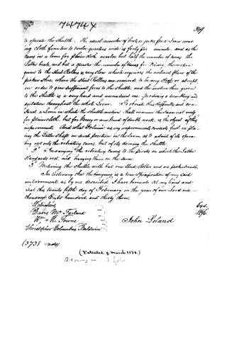 Page 10


U.S. Patent and Trademark Office · Google Patents
Show the transcription Hide (3,320 words)
Machine transcription (LightOnOCR) of the pages as scanned by the USPTO, most of them the handwritten copies made when the records were restored after the 1836 fire. Not checked; it can misread handwriting, so compare it with the scan.
Page 1.
7474X
J. Leland.
Loom.
Patented Mar. 9, 1833.
Fig. 1.
Fig. 3.
Fig. 2.
Page 2.
74744X March 9, 1833 341
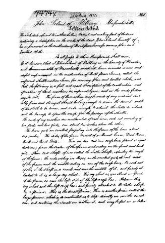
John Island of Millbury, Massachusetts,
Letters Patent
The Schedule referred to in the Letters Patent and making part of the same
containing a description in the words of the said John Island himself of
his improvement in the construction of Broad Power Looms for weaving plain and
Twillled cloth.
To all people to whom these presents shall come,
Be it known, that I John Island of Millbury, in the County of Worcester,
and Commonwealth of Massachusetts, machine, have invented a new and
useful improvement in the construction of Broad Power Looms, called the
improved Shuttlemotion Loom, for weaving plain and twilled cloths, and
that the following is a full and exact description of the construction and
operation of said machine, as improved by me, and in the words following, to wit: The frame of the machine may be made of any material suit
ably firm and strong, and should be long enough to receive the desired width
of the cloth to be woven, and wide enough to admit the Slathe to vibrate
and the harnes to open the warp for the passage of the shuttle.
The ends of my machine are constructed of cast iron, each end consisting of
two posts and two girts, one about ten inches above the other.
The lower girts are crooked projecting into the frame of the loom about
six inches. The sides of the frame consist of a Broad beam, Dead Beam,
Back and Front Girts. There are two cast iron cross bars, placed at equal
distances from the centre of the frame and resting on the front and back
girts. There is a shaft of iron called the Slathe Shaft, extending the length
of the frame, the ends resting in Boxes on the crooked girts at each end
of the frame and the middle resting on one of the cross bars. On each end
of this Slathe Shaft is, a crank and near the middle of it, and firmly at
tached to it is, a large cog wheel. This cog wheel as you stand in front
of the frame, is near the left side of the left cross bar. Between this
cog wheel and the left cross bar, and firmly attached to the Slathe Shaft
is, a pinion. This is the small pinion. There is another pinion called the
large pinion, which is so constructed as to slip directly on over the small
one, and contains the small one within it, and may be put on or taken
Page 3.
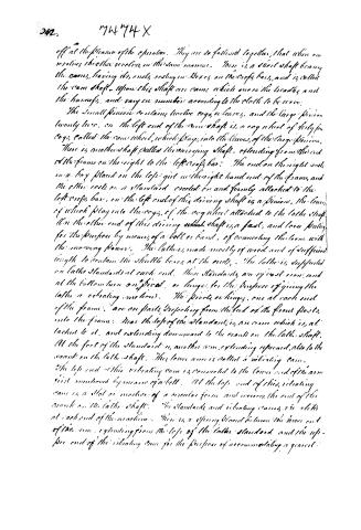
off at the pleasure of the operator. They are so fastened together, that when one revolves, the other revolves, in the same manner. There is a short shaft bearing the cams, having its ends resting in boxes on the cross bars, and is called the cam shaft. Upon this shaft are cams, which move the broads and the harness, and vary in number according to the cloth to be woven.
The small pinion contains twelve cogs or leaves, and the large pinion twenty-two. On the left end of the cam shaft is a cog wheel of forty-four cogs, called the cam wheel, which plays into the leaves of the large pinion.
There is another shaft called the sweeping shaft, extending from the end of the frame on the right to the left cross bar. The end on the right rests in a box placed on the left girt in the right hand end of the frame, and the other rests on a standard erected on and firmly attached to the left cross bar. On the left end of this driving shaft is a pinion, the leaves of which play into the cogs of the cog wheel attached to the lathe shaft. On the other end of this driving shaft is a fast, and loose pulley, for the purpose, by means of a belt or band, of connecting the loom with the moving power. The lathes, made mostly of wood and of sufficient length to contain the shuttle boxes at the ends. The lathes are supported on lathe standards at each end. These standards are of cast iron, and at the bottom turn on pivots or hinges for the purpose of giving the lathe a vibrating motion. The pivots or hinges, one at each end of the frame, are on parts projecting from the feet of the front posts into the frame. Near the top of the standards is an arm which is attached to it, and extending downward to the crank on the lathe shaft. At the foot of the standard is another arm extending upward, also to the crank on the lathe shaft. This lower arm is called a vibrating cam. The top end of this vibrating cam is connected to the lower end of the arm just mentioned by means of a belt. At the top end of this vibrating cam is a slot or groove of a circular form and receives the end of the crank on the lathe shaft. The standards and vibrating cams are alike at each end of the machine. There is a spring band between the lower end of the arm extending from the top of the lathe standard and the upper end of the vibrating cam for the purpose of accommodating a greater
Page 4.
343.
your Beam: with which the loom is contemplated to be finished. It is not intended however to be used when the loom is worked with a common wire or leather friction, but when it is thus worked, they may be secured up fast together. On the left hand side of the large cog wheel is inserted a pin called the stud roller, and is confined in a slot, and movable at pleasure. The office of this is to throw the shuttle. Near the cog wheel on the other shaft, at the left of it is the picker or shuttle treadle. This hangs on a hinge attached to the back side of the frame. Upon this treadle and directly against the lowest point in the cog wheel is attached the picker shoe. This shoe presents an inclined plane; and receiving the stud roller of the cog wheel revolves. Near the hinge of the treadle is a wire or spring contained in a tube or barrel, after the manner of the patent balance, attached to the frame at the upper end, and the lower end attached to the treadle; to raise the treadle back to its place after it has been depressed by the stud roller. Two strong staff pulleys are placed in the forefront of the machine, at equal distances from the centre of the loom, the one on the left being nearly over the picker treadle, the other about two feet from it at the right. A small friction roller or pulley is placed between these two pulleys, but nearer to the left pulley than the other, being at a distance a little more than the thickness of the end of the picker treadle. One end of the staff is confined to one of the pulleys on the outward side of it and passes over the friction pulley to where it is confined; as mentioned above to the treadle, and then to the outward side of the pulley where it is also fastened. The strong slats are firmly attached to the two outside pulleys mentioned before. At the upper ends of these slats are attached strings or cords connected at the other ends to the pickers that throw the shuttle. Between these pickers are feeders hanging on hinges at the backside of the loom. The feeders are connected to the harness by means of strings or wires, and the harness is suspended from the harness rollers. On the front side of the loom is the cloth beam, accommodated on the left hand end, with a catch which is moved forward by a dog and thus the cloth is taken up as fast as it is woven.
Explanation of the Drawings.
Page 5.
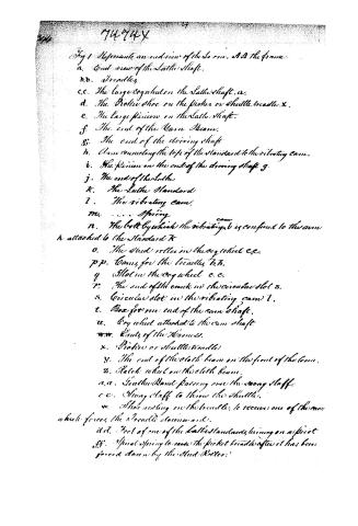
Fig 1 Represents an end view of the Loom. A.D the frame.
a. End view of the Lathe Shaft.
b.b. Breeches
c.c. The large cogwheel on the Lathe Shaft. a.
d. The Picket Shoe on the Picket or Shuttle treadle x.
e. The large Pinion on the Lathe Shaft.
f. The end of the Main Beam.
g. The end of the Driving Shaft
h. Arm connecting the top of the Standard to the vibrating cam.
i. The Pinion on the end of the driving Shaft g.
j. The end of the Lathe
k. The Lathe Standard
l. The vibrating cam.
m. Spring
n. The bolt by which the vibrating cam is confined to the arm h attached to the Standard k
o. The Stud roller in the cog wheel c.c.
p.p. Bands for the treadles b.b.
q. Slot in the cog wheel c.c.
r. The end of the crank in the circular slot s.
s. Circular slot in the vibrating cam l.
t. Box for one end of the cam shaft.
u. Cog wheel attached to the cam shaft.
w.w. Ends of the Harness.
x. Picket or Shuttle treadle
y. The end of the cloth beam on the front of the Loom.
z. Ratchet wheel on the cloth beam.
a.a. Leather Band passing over the swing staff.
c.c. Swing staff to throw the shuttle.
w. Shoe resting on the treadle, to receive one of the cams which forces the treadle downwards.
d.d. Foot of one of the Lathe Standards, turning on a pivot
f.f. Spiral spring to raise the picket treadle after it has been forced down by the Stud Roller.
Page 6.
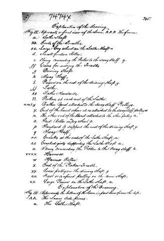
Explanation of the Drawing.
Fig. II. Represents a front view of the Loom. B.B.B. The frame.
a. Lathe Shaft.
bb. Ends of the Treadles.
cc. Large Cog wheel on the Lathe Shaft a.
d. Small friction Roller.
e. String connecting the Treadle to the Swing Staff g.
ff. Gears for moving the Treadles.
g. Driving Shaft.
h. Swing Staff.
i. Pinion on the end of the driving Shaft g.
jj. Lathe.
kk. Lathe Standards.
ll. Pickets at each end of the Lathe.
n.m.i.y. Leather Band attached to the Swing Staff Pulley g.
y. End of the band where it is attached to the Swing Staff Pulley w.
n. The other end of the Band attached to the other Pulley u.
o. Stud Roller in Cog wheel c.
p. Standard to support the end of the driving Shaft g.
q. Swing Staff.
rr. Brackets at the ends of the Lathe Shaft a.
s.s. Crossed girts supporting the Lathe Shaft a.
u. String connecting the Picket to the Swing Staff h.
v.v.v.v. Harness.
w. Harness Roller.
x. End of the Picket Treadle.
yy. Loose Pulley on the driving Shaft g.
nn. Fast or confined Pulley on the same Shaft.
zz. Large Pinion on the Lathe Shaft a.
Explanation of the Drawing.
Fig. III. Represents the bottom of the Loom in part seen from the top.
AA. The Lower Side Pieces.
a. The Lathe Shaft.
Page 7.
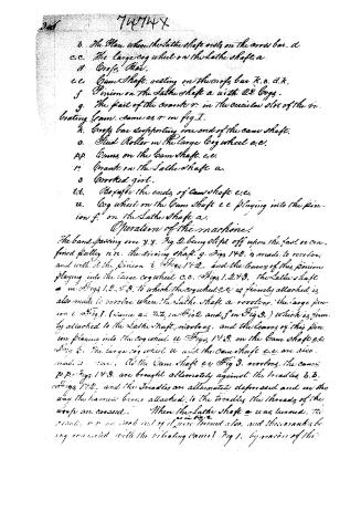
b. The place where the lathe shaft rests on the cross bar.
c.c. The large cog wheel on the lathe shaft a.
d. Cross Bar.
e.e. Cam Shaft, resting on the cross bar K.B.d.K.
f. Pinion on the lathe shaft a with 22 cogs.
g. The part of the crank r in the circular slot of the vibrating beam. Same as r in fig I.
k. Cross bar supporting one end of the cam shaft.
o. Stud Roller in the large cog wheel e.e.
p.p. Cams on the cam shaft e.e.
r.r. Cranks on the lathe shaft a.
s. Grooved joint.
t.t. Grooves in the ends of cam shaft e.e.
u. Cog wheel on the cam shaft e.e playing into the pinion f on the lathe shaft a.
Operation of the machine:
The band passing over y.y. Fig 2 being slipped off upon the fast or confined pulley n.n. the driving shaft g. Fig 142. is made to revolve, and with it the pinion i. Fig 142. and the leaves of this pinion playing into the large cog wheel c.c. Fig 1.243. the lathe shaft a in Figs 1.2.43. to which the cog wheel c.c. is firmly attached, is also made to revolve when the lathe shaft a revolves. The large pinion c. Fig 1. (same as t.t. in Fig 2 and f in Fig 3.) which is firmly attached to the lathe shaft, revolves, and the leaves of this pinion playing into the cog wheel u. Fig 143. on the cam shaft e.e. Fig 3. The large cog wheel u and the cam shaft e.e. are also made to revolve. As the cam shaft e.e. Fig 3. revolves, the cams p.p. Fig 143. are brought alternately against the treadles b.b. Fig 142. and the treadles are alternately depressed and in this way the harness being attached to the treadles the threads of the warp are covered. When the lathe shaft a was turned, the cranks r.r. on each end of it were turned also, and these cranks being connected with the vibrating cams 1 Fig 1. by means of the
Page 8.
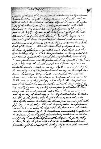
motion of the ends of the cranks into the circular slots (3. Fig 1 represents the circular slot in one of the vibrating cams, and 2. fig 1. the end of one of the cranks.) the vibrating cams were depressed, and as the upper ends of the vibrating cams are united, or connected to the Lathe Standards k. Fig 1. and kk in Fig 2. by means of the arms, as seen at h. Fig 1. by means of the bolts as at n. Fig 1. the Lathe Standards k and with it the Lathe j. Fig 1. (the Standards at both ends of the loom being alike, and moved in the same way and turning on a pivot, as at d. d. Fig 1.) is carried toward the back of the loom. When the Lathe Shaft a began to revolve, the large cog wheel 2. e. Figs 1. 2. 3. revolved with it, and the stud roller 2. Fig 1. 2. 4. 3 being attached to the cog wheel 2. e. was carried against the inclined plane of the Picker shoe d. Fig 1. and forced down and this Picker shoe being upon the Picker treadle a. Figs 1. 4. 2. the treadle was forced downwards also, and the leather band or strap m. n. l. y. Fig 2. (same as a. a. Fig 1.) the vibrating end of the Picker treadle resting on the strap between the pulleys 2. 4. d. Fig 2. was carried down at the same time, and as this strap is confined at each end m. n. y. to the two swing staff pulleys 2. 4. w. Fig 2. the two pulleys were both turned towards each other and as the swing staff pulleys 2. 4. y. of Fig 2. (same as c. c. Fig 1.) are firmly attached to the swing staffs, moved towards each other in the same manner and by means of the strings u. 7. e. Fig 2. attached is the Pickers 2. 2. Fig 2. the pickers were brought towards each other also. And by this motion the shuttle was thrown from one end of the Lathe j. j. Fig 2. to the other. When the large cog wheel had performed one revolution, or when the stud roller had forced down the Picker treadle, and passed by it, the treadle was immediately brought back to its place by means of the spiral spring contained in the bar. rod f. f. Fig 1. and this left end of the strap on the pulley 2. Fig 2. loose, so that the force with which the shuttle was driven, from the right hand end of the Lathe j. Fig 2. to the other end will
Page 9.
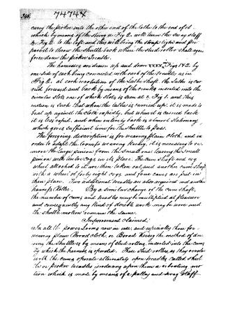
carry the picker into the other end of the lathe to the end of it — which, by means of the string in Fig 2, will turn the swing staff in Fig 2 to the left and this will bring the strap tight and prepare it to throw the shuttle back where the stud roller shall again force down the picker treadle.
The harnesses are drawn up and down in Figs 1 & 2, by one side of each being connected with each of the treadles as in Fig 2, at each revolution of the Lathe shaft. The Lathe is carried forward and back by means of the cranks inserted into the circular slots, one of which slots is seen at 5, Fig 1, and this motion is such that when the lathe is carried up, it is made to beat up against the cloth rapidly, but when it is carried back it is less rapid, and when entirely back is almost stationary, which gives sufficient time for the shuttle to pass.
The foregoing description is for weaving plain cloth, and in order to adapt the loom to weaving kersey, it is necessary to remove the large pinion from the small one, leaving the small pinion with its bevel cogs in its place. The cam shaft and cog wheel attached to it are then taken out, and another cam shaft with a wheel of forty-eight cogs, and four cams are put in their place. Two additional treadles are also required and another harness roller. By a similar change of the cam shaft, the number of cams and treadles may be multiplied at pleasure and consequently any kind of double work may be wove and the shuttle motion remain the same.
Improvement claimed:
In all the power looms now in use, and especially those for weaving plain Broad cloth, or Broad Kersay the method of driving the shuttle is by means of stud rollers, inserted into the cams by which the harness is operated. These stud rollers, as they revolve with the cams operate alternately upon treadles called shuttle or picker treadles, producing upon them a vibrating motion which is made by means of a pulley and swing staff
Page 10.
to operate the shuttle. The usual number of beats or jerks for a loom weaving cloth from ten to twelve quarters wide is forty per minute, and as the cams in a loom for plain cloth revolve but half the number of times the Lathe beats, and but a quarter the number of times for heavy, the motion given to the Stud Rollers is very slow which requires the inclined plane of the picker shoe, where the Stud Rollers are received, to be very steep or abrupt, in order to give sufficient force to the shuttle, and the motion thus given to the shuttle is a very hard and unnatural one, producing a trembling and agitation throughout the whole loom. To obviate this difficulty and construct a loom in which the shuttle motion shall remain the same not only for plain cloth, but for heavy or any kind of double work, is the object of this improvement. And what I claim as my improvement consists first in placing the Lathe Shaft in such position in the loom, as to admit of its operating not only the vibrating cams, but of its driving the shuttle.
2° Arranging the vibrating cams to the pivots on which the Lathe Standards rest, and hanging them on the same.
3° Motoring the shuttle with but one Stud Roller and one picker treadle.
In testimony that the foregoing is a true Specification of my said improvement, as by me described, I have hereunto set my hand and seal this twenty fifth day of February in the year of our Lord one thousand Eight hundred and thirty three.
Witnesses
Davis M. Farland
Wm. R. Towne
Christopher Columbus Baldwin
John Leland
(3738 words)
(Patented 9. March 1836.)
Drawing ~ 1st (cleo)
Published accounts: journal notice
Notice in the monthly list of patents, with remarks
Journal of the Franklin Institute, new ser., vol. 12 (1833), p. 175 · View the page
20. For an improvement in the Broad Power Loom; John Leland, Milbury, Worcester county, Massachusetts, March 9.
Remarks. After describing the construction of the loom, it is observed that in all the power looms now in use, the shuttle is driven by means of stud collars inserted into the cams by which the harness is operated; and that the usual number of beats, or jerks, for a loom weaving cloth of from ten to twelve quarters wide, is forty per minute; and as the cams in a loom for plain cloth revolve but half the number of times the lathe beats, and but a quarter of the number for kersey, the motion given to the stud rollers is very slow, which requires the inclined planes of the picker shoe, where the stud rollers are received, to be very steep or abrupt, in order to give sufficient force to the shuttle; and the motion thus given to the shuttle is a very hard and unnatural one, producing a trembling and agitation throughout the whole loom. To obviate this difficulty, and construct a loom in which the shuttle motion shall remain the same, not only for plain cloth but for kersey, or any kind of double work, is the object of this improvement, which consists, first, in placing the lathe shaft in such a position in the loom as to admit of its operating not only the vibrating cams, but of its driving the shuttle. Secondly, in ranging the vibrating cams to the pivots on which the lathe standards rest, and hanging them to the same. Thirdly, in motioning the shuttle with but one stud roller, and one picker treadle.
About this record
- Patentee
- DATAMP
- Date
- the Name and Date index of patents, DATAMP, USPTO records
- Invention
- DATAMP
- Listed in
- the Name and Date index of patents, DATAMP, USPTO records, Jim Shaw's X-patent list, the Journal of the Franklin Institute, Burke's List of Patents (1847)
- Burke's 1847 Patent Office list gives the same patent.