

Drawings and documents
National Archives restored drawings: drawing
Richard Walker's Patent Drawing for a Water Wheel

National Archives, Restored Patent Drawings (Record Group 241) · Full-size scan at the National Archives · Catalog record
Show the text on the drawing Hide (96 words)
Words on the drawing as machine-read by the National Archives; not checked. Useful mainly for searching.
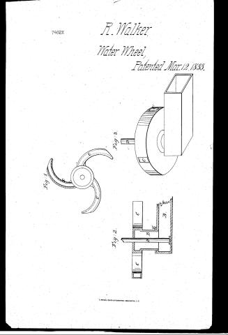
138. HYDRAULIC MOTORS. / 11 / Turbines, / Richard Watker / 16 / $150 [100] Bottom Supply / Water Wheel, / CLASSIFICATION / Patented 12 12th March 1833, / 7482-X / DIVISION. / Eig,1, / Fig.3, / Fid.2. / References. / Fid.1. view of bollom of wheel, / Fid.2. section of wheel and conductor, / I'v 3 perspective of wheel with solid richfrom rom below.) / Patent Office Dee 9. 1841 / A. conductor. B. cylinder. C. ar C'outlets onsolidminabed, / D.shaft. Encircular plate on conductor, / Made under the direction of the Comminismer of Patents / in conformity with act of bong rep 3d March 1837 / Md Ellmoth / Patults,
USPTO scan
The patent as scanned by the USPTO
-
 Page 1
-
 Page 2
-
 Page 3


U.S. Patent and Trademark Office · Google Patents
Show the transcription Hide (558 words)
Machine transcription (LightOnOCR) of the pages as scanned by the USPTO, most of them the handwritten copies made when the records were restored after the 1836 fire. Not checked; it can misread handwriting, so compare it with the scan.
Page 1.
7482X
R. Walker,
Water Wheel,
Patented Mar. 12, 1833.
Fig. 1
Fig. 3
Fig. 2
Page 2.
7482x
Mar 12, 1823
Richard Walker
Letters Patent
The schedule referred to in these Letters Patent and making part of the same containing a description in the words of the said Richard Walker himself of his improvement in the construction of Water Wheels & applying Water thereto.
To all to whom these presents shall come
It is known that I Richard Walker of the County of Stafford & State of New Hampshire have invented a new & useful improvement in the construction of Water Wheels & in the application of Water to the wheel & that the following is a full & exact description of the construction & operation of the said Wheel as invented by me.
The wheel represented by the drawing & Model is six feet in diameter one foot thick with an iron shaft four inches in diameter this shaft is to stand perpendicular on a pivot in the bottom of the conductor. From the center of the wheel around the shaft extends a vast hollow cylinder downwards into the conductor. Upon the top of which is to be a circular plate this which the cylinder passes so as to make it water tight. The cylinder about one foot in diameter with the lower end open receives the water as it is forced from the conductor & conducts it into the center of the wheel. From the center of the wheel the water is forced out at the rim. There three semicircular buckets or hollow arms to the opposite parts of the rim. The buckets or winding outlets are three inches wide by nine deep making the column of water passing through the wheel nine inches square. The space of the inside of said buckets arms or outlets at the space of the semidiameter of the wheel & the continual pressure of water on the outer circle gives the wheel its motion. Further said wheel may be built of either wood or cast iron & when built for tide water is to present an entire smooth surface excepting the outlets in the rim. It will work as well under water as out of water but may be made for ordinary purposes with only hollow semicircular arms.
D. W.
Page 3.
7482x
Mar. 12, 1833
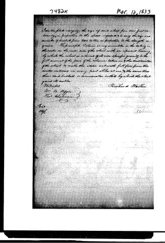
I have templates varying the size of said wheel from two feet to twenty-five in proportion to the space required, to vary the size and number of buckets from two to ten in proportion to the strength required. The principle I claim as my invention is the taking in the water on the under side of the wheel with an upward bearing by which the wheel is relieved of its own specific gravity to the full amount of the force of the column taken in & the construction of the wheel to make the water act with full force from the center outward on every part alike at one & the same time thru said buckets or semicircular outlets by which the wheel gains its motion.
Witnesses
Richd. Walker
Wm. B. Higgin
Geo. Schafman
Bvd.
Hgl.
346005
Published accounts: journal notice
Notice in the monthly list of patents, with remarks
Journal of the Franklin Institute, new ser., vol. 12 (1833), p. 178 · View the page
26. For an improved Water Wheel; Richard Walker, Milton, Strafford county, New Hampshire, March 12.
Remarks. There is much resemblance between this water wheel, and the rotary steam engine just described. The wheel is to run horizontally like Wing's and most of the other reaction wheels, and from its centre to its periphery, it is to have three channels, or water ways, constructed like the four in the foregoing rotary engine. The water is to be conducted down through a vertical trunk, then horizontally, and then up through a tube into the centre of the wheel on its lower side. The pressure of the water thus forces the wheel upwards, and counteracts the effects of its own gravity, and that of its appendages. The wheel must, of course, fit closely to the tube through which it receives its supply. she It appears that the patentee makes large calculations upon the curved form of the outlets, as he informs us that "the continual pressure of water on the outer circle, gives the wheel its motion." We can assure him, however, that he may apply our remark respecting the rotary engine to his wheel; make it a drum, leaving only the proper openings in the periphery, and he will lose nothing in its action, whilst he will gain something in the labour of construction. If the "continual pressure of the water on the outer circle gives the wheel its motion," is there not an equal pressure upon the inner circle, and what is the effect of that? The claim is to the "taking in the water on the under side of the wheel, with an upward bearing, by which the wheel is relieved of its own gravity, to the full amount of the force of the column of water taken in; and the construction of the wheel to make the water act with full force from the centre outward in every part alike at one and the same time, through said buckets or semicircular outlets by which the wheel gains its motion." We cannot say any more in favour of the novelty of the upward pressure, than we have said of the novelty and utility of the curved channels.
About this record
- Patentee
- DATAMP
- Date
- the Name and Date index of patents, DATAMP, USPTO records
- Invention
- DATAMP
- Listed in
- the Name and Date index of patents, DATAMP, USPTO records, Jim Shaw's X-patent list, the Journal of the Franklin Institute, Burke's List of Patents (1847)
- Burke's 1847 Patent Office list gives the same patent.