

Drawings and documents
National Archives restored drawings: drawing
George Page's Patent Drawing for a Mortising Machine

National Archives, Restored Patent Drawings (Record Group 241) · Full-size scan at the National Archives · Catalog record
Show the text on the drawing Hide (39 words)
Words on the drawing as machine-read by the National Archives; not checked. Useful mainly for searching.
144. WOOD WORKING MACHINES. / Mortising, Chisel Cutters. / 1.50 / (NewDrawing made from Model Mar. 5.1870.) / # #7484 George Page. / CLASSIFICATION / 7484X X / Mortising Machine. / DIV SION. / Pat a Mar. 13.1833.
USPTO scan
The patent as scanned by the USPTO
-
 Page 1
-
 Page 2
-
 Page 3
-
 Page 4
-
 Page 5
-
 Page 6
-
 Page 7


U.S. Patent and Trademark Office · Google Patents
Show the transcription Hide (1,961 words)
Machine transcription (LightOnOCR) of the pages as scanned by the USPTO, most of them the handwritten copies made when the records were restored after the 1836 fire. Not checked; it can misread handwriting, so compare it with the scan.
Page 1.
7484X
(New Drawing made from Model Mar. 5.1870.)
George Page.
Mortising Machine.
Pat’d Mar. 13.1833.
Page 2.
7484 X March 13, 1833
301
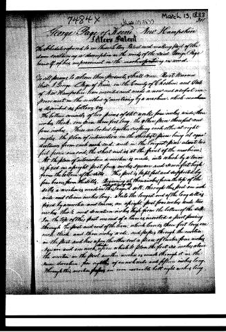
George Page of Keene, New Hampshire
Letters Patent
The schedule referred to in these Letters Patent and making part of the same containing a description in the words of the said George Page himself of his improvement in the machine for tying in cords.
To all persons to whom these presents shall come, Be it known that I George Page of Keene in the County of Cheshire and State of New Hampshire have invented and made a new and useful improvement in the method of mortising by a machine, which machine is described as follows viz:
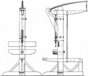
The bottom consists of two pieces of flat work, four inches wide, three inches thick, one piece three feet long, the other piece three feet and four inches. These are locked together crossing each other at right angles, the place of intersection in the shortest piece being at equal distances from each end, and in the longest piece about two feet from one end, the short end is at the front of the machine.
At the place of intersection a mortise is made, into which by a tenon is fixed an upright post four inches square and seven feet high from the bottom of the sills. This post is kept fast and supported by four braces from the sills. Beginning at three inches from the top of the sills a mortise is made in the longest sill. Through this post one inch wide and eleven inches long. Into the longest end of the long sill is fixed by a mortise and tenon, an upright post four inches wide, two inches thick and sixteen inches high from the bottom of the sill.
In the top of this post one end of a lever is inserted a post passing through the post and end of the lever, which lever is three feet long, one inch thick and three inches wide, and passes through the mortise in the post and has upon the other end a piece of timber four inches square and one inch upon which to place the foot six inches above the mortise in the post another mortise is made through it in the same direction, five eighths of an inch wide and fifteen inches long. Through this mortise passes an iron movable but eight inches long,
Page 3.
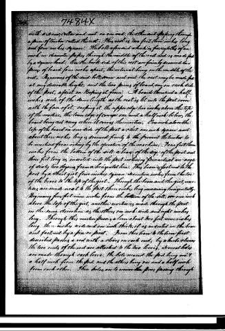
with a strong collar and nut on one end, the other end passing through a piece of timber called the nest. This nest is two feet three inches long and four inches square. The hole at the end which is five eighths of an inch in diameter passes through the middle of the nest and is made fast by a square head. On the back side of this nest are firmly secured two pieces of board four inches apart, the interval being in the middle of the nest. By means of the said collar, screw and nut the nest may be made fast at any desirable height, and the two pieces of board, one on each side of the post, assist in keeping it firm. A board three and a half inches wide of the same length as the nest is let into the post even with the face of it, coping it. The upper edge two inches above the top of the mortice, the lower edge of course one and a half inch below, the board being set away where it covers the mortice. One inch above the top of the board on one side of the post a slot one inch square and about three inches long is secured firmly to the post to prevent the timber to be moved from riding by the operation of the machine. Four feet three inches from the bottom of the sill a brace of the size of the post and three feet long is inserted into the post inclining forwards at an angle of nearly two degrees from a horizontal line. This brace is fastened to the post by a short girl four inches square sixteen inches from the toe of the brace to the top of the girl. Through the brace and the girl mortices are made next to the post three inches long measuring horizontally. Beginning five feet nine inches from the bottom of the sill, one inch above the top of the girl, another mortice is made through the post in the same direction as the others one inch wide and eight inches long. Through this mortice passes a lever about two feet nine inches long three inches wide and one inch thick, it is inserted in the brace and fastened by a pin or pivot. From this lever to the lever first described passes a rod with a clevis on each end, by which clevis the two ends of the rod are attached to the two levers, several holes are made through each lever. The hole nearest the post being one and a half inch from the post and the others being one and a half inch from each other. These holes are to receive the pins passing through
Page 4.
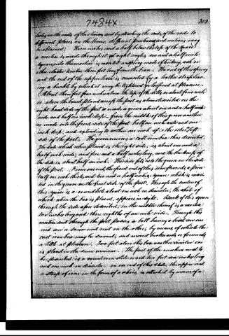
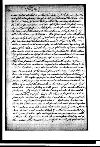
Holes in the ends of the levers, and by attaching the ends of the rods to different places on the levers, different powers and motions may be obtained. Three inches and a half below the top of the space a mortice is made through it at right angles, one and a half inch square; into this mortice is inserted a spring made of hickory, ash, or other elastic timber, three feet long from the base. The end of this spring and the end of the upper lever is connected by a leather strap having a buckle by which it may be tightened or loosened at pleasure. About three feet four inches above the top of the talls or about four inches above the board plank nor of the post as above described on the right-hand side of the post is made a groove about one and a half inch wide and half an inch deep. From the middle of this groove another is made into the front side of the post, half an inch wide and one inch deep, and extending to within one inch of the other, left side of the post. The groove receives a cast iron box thus described. The side which when placed in the right side, is about one and a half inch wide, and five and a half inches long, and the thickness of the side is about half an inch. This side fits into the groove on the side of the post. From one end, the front end of this iron proceeds a piece half an inch thick, and two and a half inches square, which is inserted in the groove on the front side of the post. Through the center of this square is a round hole about one inch in diameter, the hole of which when the box is placed, appears in sight. Back of this square through the side as before described, in the middle thereof is a mortice two inches long and three eighths of an inch wide. Through this mortice and through the post passes a bolt having a head on one end and a screw and nut on the other, by means of which the cast iron box may be secured, and moved back wards or forwards a little at pleasure. Two feet above this box another similar one is placed in the same manner. The part of the machine next to be described is a round iron slide about two feet one inch long and one inch in diameter. On one end of this slide, the upper and a strap of iron in the form of a chain is attached by means of a
Page 6.
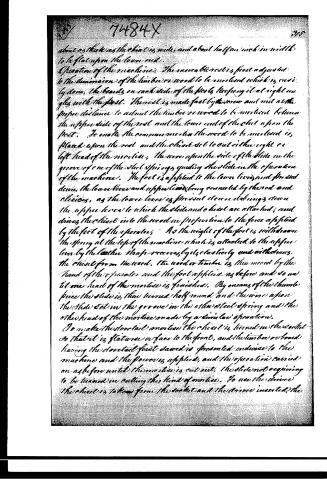
about as thick as the chest is wide, and about half an inch in width to be flat upon the lower end.
Operation of the machine. The movable rest is first adjusted to the dimension of the timber or wood to be mortised which is easily done, the boards on each side of the posts keeping it at right angles with the post. The rest is made fast by the screw and nut at the proper distance to admit the timber or wood to be mortised between the upper side of the rest and the lower end of the chest upon the post. To make the common mortice the wood to be mortised is placed upon the rest and the chest set to cut either right or left head of the mortice, the wire upon the side of the slide in the groove of one of the steel springs guiding the slide in the operation of the machine. The foot is applied to the lower lever and pressed down, the lower lever and upper lever being connected by the rod and clevises, as the lower lever is pressed down the springs draw the upper lever to which the slide and chest are attached; and drives the chest into the wood in proportion to the force applied by the foot of the operator. As the weight of the foot is withdrawn the spring at the top of the machine which is attached to the upper lever by the leather straps recovers by its elasticity and withdraws the chest from the wood. The wood or timber is then moved by the hand of the operator and the foot applied as before and so until one head of the mortice is finished. By means of the thumb piece the slide is then turned half round and the wire upon the slide set in the groove in the other steel spring and the other head of the mortice made by a similar operation.
To make the dovetail mortice the chest is turned in the socket so that it is flatwise or face to the front, and the timber or board having the dovetail first sawed is presented endwise to the machine and the power is applied, and the operation carried on as before until the mortice is cut out, the slide not requiring to be turned in cutting this kind of mortice. To use the driver the chest is taken from the socket and the driver inserted, the
Page 7.
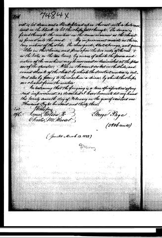
rot is let down and a block placed upon the seat with a hole mounted in the block to let the chips fall through. The draw is forced through the mortice in the same manner as the chest is forced into the seat. My improvement consists in the rotary motion of the slide, the shoe guides, steel, & springs, and grooves also in the clevis and pin upon the two ends of the rod & in the holes in the two levers, by means of which the power and motion of the machine may be increased or diminished at the pleasure of the operator. Also in the round socket in the slide, and round shank of the chest by which the dovetail mortice is cut and also by forcing to the machine a draw, by which the chips are cleared from the mortice.
In testimony that the foregoing is a true specification of my said improvement, as described I have hereunto set my hand this twenty seventh day of February in the year of our Lord one thousand Eight hundred and thirty three.
Witnesses
James Wilson Jr
Charles McMurat
George Page
(2506 words)
(Granted March 13, 1833)
Published accounts: journal notice
Notice in the monthly list of patents, with remarks
Journal of the Franklin Institute, new ser., vol. 12 (1833), p. 179 · View the page
29. For a Mortising Machine; George Page, Keene, Cheshire county, New Hampshire, March 13.
Remarks. This machine is described at great length, but the drawing which accompanies it is but indifferently executed. There is enough, however, to show that, in its general operation, it resembles most of the mortising machines which have preceded it; and, indeed, as there are many of them, it is scarcely to be expected that much novelty would appear in a new machine for performing this simple operation. The claims are necessarily confined to matters of mere arrangement; and most of them are of a character rather trivial; they consist in the rotary motion of a slide; a wire guide; steel springs and grooves; a clevis and pins; the increasing or diminishing the power of a lever, by holes changing its fulcrum; a round socket in the slide, and a round shank to the chisel, allowing it to be put askew; and a driver for removing the chips.
DATAMP: illustration
Illustrations from DATAMP

DATAMP (Directory of American Tool and Machinery Patents), via the Internet Archive · Archived DATAMP page
About this record
- Patentee
- DATAMP
- Date
- the Name and Date index of patents, DATAMP, USPTO records
- Invention
- DATAMP
- Listed in
- the Name and Date index of patents, DATAMP, USPTO records, Jim Shaw's X-patent list, the Journal of the Franklin Institute, Burke's List of Patents (1847)
- Burke's 1847 Patent Office list gives the same patent.