

Drawings and documents
National Archives restored drawings: drawing
Louis Bayha and Frederick Rapp's Patent Drawing for a Sausage Cutter

National Archives, Restored Patent Drawings (Record Group 241) · Full-size scan at the National Archives · Catalog record
Show the text on the drawing Hide (72 words)
Words on the drawing as machine-read by the National Archives; not checked. Useful mainly for searching.
12- / 17. / Barr è / CLASSIFICATION / Lausage Cutter. / 7515-X II / Patented April 8th 1833 / References. / eylinder ditached / Carriage / (one / side / Pegs / Pegs on bylinder / ditto / k. / Cog wheel / Bevel wheel. / wheel / n. Segment what. / Racks. / Severs with weights / Patent Office 30thune 1838, / Made under the direction of the Commisioner of / Patents in conformity with act 3d March 1837. / MLCUmorth / Commisioner of Bit
USPTO scan
The patent as scanned by the USPTO
-
 Page 1
-
 Page 2
-
 Page 3
-
 Page 4


U.S. Patent and Trademark Office · Google Patents
Show the transcription Hide (900 words)
Machine transcription (LightOnOCR) of the pages as scanned by the USPTO, most of them the handwritten copies made when the records were restored after the 1836 fire. Not checked; it can misread handwriting, so compare it with the scan.
Page 1.
7515X
Bayha & Rapp.
Sausage Cutter.
Patented Apr. 8, 1833.
THE NORRIS PETERS CO., WASHINGTON, D.C.
Page 2.
7515X
April 8, 1833
Louis Bayha and Frederick Rapp
Letters Patent
The Schedule referred to in this Letter Patent and making part of the same containing a description in the words of the said Louis Bayha and Frederick Rapp themselves of their improvement in the machine for cutting Sausage Meat.
Be it known that we Louis Bayha and Frederick Rapp of Hunting Ohio County and State of Virginia have made an improvement in the machine for cutting Sausage Meat which is described as follows. This machine consists of a frame which supports the machinery and carries a carriage and block on which the meat is placed and cut. Knives for cutting the meat and the arms and levers by which they are worked. A cylinder containing projections which raise the knives. A cog wheel, bevel wheel and pinion which move the rack and carriage and a rack and segment wheel for moving the carriage. The frame is constructed by mortising and tenoning together four uprights, two girdles and two cross pieces. From the top two arms project to receive the ends of the levers placed over the arms of the knives. Also on the top is placed a rail having partitions in it through which the before mentioned levers work. The frame is about 6 feet high, 6 feet long and 3 feet wide. The carriage and block. The carriage is about 3 feet long, 20 inches wide and 16 inches deep. The sides and ends are movable and can be taken off. At one end of the carriage is set an arm about 2½ feet long to which is placed the rack and segment wheel to be hereafter described. The block on which the meat is cut is about 14 feet 2 inches long, 18 inches wide and 16 inches deep. It is placed upon the carriage and when worn can be raised up and is about 4 inches above the bottom of the carriage. The carriage with the block
Page 3.
are placed upon rollers resting on the sides of the frame. The knives and arms & levers for moving them. There may be from four to sixteen knives more or less. Each knife is about 13 inches long and 6 inches deep, made of the best steel with a sharp cutting edge. It is fastened by bolts or screws to an arm about 3½ feet to 4 feet long. A fly or projection is put on each arm about 2 feet from the knife. It is made each to work through an opening in a crop piece. A lever is placed over each arm and knife having a weight on it for giving force to the knife. This lever turns on a pivot placed on the frame. The knife is raised about 8 or 9 inches by the projections on the cylinder to be hereafter described.
The cylinder containing the projections or pins which work the knives. The cylinder extends the length of the frame and about 6 or 8 inches in diameter. It turns on gudgeons in the frame by means of a crank. The rows of pins are put upon this cylinder in a spiral direction so that each knife will be moved three at each revolution of the cylinder.
Cog Wheel, Bevel Wheel and Pinion, which move the rack and carriage by two racks and segment wheel placed between them. A pinion placed on the end of the cylinder turns a cog wheel turning on gudgeons in the frame. This turns a main wheel by a bevel wheel fixed on the same axle as the cog wheel. The main wheel is fixed on an axle or shaft about 4 feet long. On the lower end of this shaft is a segment cog wheel which works in two racks (one on each side) and moves the carriage forward and backward.
Operation. The meat to be cut is placed on the block in the carriage. Motion is given to the cylinder by any convenient power. The pins on the cylinder give motion to the pinions by raising the arms. The weight on the levers placed over the arms and them down with force. The pinion on the end of the cylinder gives motion to the cog wheel. The bevel wheel with axle gives motion to the main wheel. This gives motion to the segment wheel at the lower end of the shaft which works into the racks placed on each side of it alternately which move the carriage.
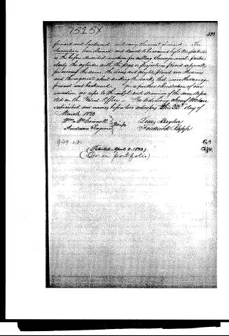
Page 4.
forward and backward, and carry the meat forward. The invention herein claimed and deemed to be secured by the aforesaid patent is the before described machine for cutting sausage meat, particularly the cylinder with the flaps or projections placed separately forming the arms, the levers and weights placed on the arms and the segment wheel working the racks that move the sausage forward and backward. For a further illustration of our invention we refer to the model and drawing of the same deposited in the Patent Office. In testimony whereof we have subscribed our names before two witnesses this 20th day of March 1833.
Wm McConnell 3 Minifs
Andrew Blagden
Lewis Mayhra
Frederick Rapp
(Patented April 8, 1833)
(On an portfolio)
Published accounts: journal notice
Notice in the monthly list of patents, with remarks
Journal of the Franklin Institute, new ser., vol. 12 (1833), p. 237 · View the page
12. For a Machine for Cutting Sausage Meat; Lewis Bayha, and Frederick Rapp, Wheeling, Ohio county, Virginia, April 8.
Remarks. Knives are fixed on the ends of pieces of timber which are raised vertically by means of cams, or lifters, projecting from a revolving cylinder. The meat is placed upon a log or block, which forms the bottom of a trough for containing it. From the revolving shaft of the lifters, and by means of a shaft and bevil wheels, motion is communicated to the block containing the meat, which being thereby moved backward and forward, causes the knives to cut on different parts. The claim is to "the before described machine; particularly the cylinder with the pegs or projections placed spirally for moving the arms; and the segment wheel, working the racks that move the carriage backward and forward." If a claim cannot be sustained to the general arrangement of the machine, which has but little novelty, it certainly cannot to the "cylinder with the pegs," and "the segment wheel," that has none.
About this record
- Patentee
- DATAMP
- Date
- the Name and Date index of patents, DATAMP, USPTO records
- Invention
- DATAMP
- Listed in
- the Name and Date index of patents, DATAMP, USPTO records, Jim Shaw's X-patent list, the Journal of the Franklin Institute, Burke's List of Patents (1847)
- Burke's 1847 Patent Office list gives the same patent.