

Drawings and documents
National Archives restored drawings: drawing
Eliphalet Nott's Patent Drawing for a Mica Sash

National Archives, Restored Patent Drawings (Record Group 241) · Full-size scan at the National Archives · Catalog record
Show the text on the drawing Hide (246 words)
Words on the drawing as machine-read by the National Archives; not checked. Useful mainly for searching.
ATION Balorific / IL / 76357 / II / ISION. / 26. STOVES & FURNACES. / ANY / [154] Stove Doors & Windows / Patent, N.° 2. / Patented 29th..June. 29th 1833. / FIG.1. 1. / FIG.2. / FIG.4. 4. / FIG.3. / C.D / ]c. / 08 / b. / b. / h. / FIG / REFERENCES. / Fig 1. Back frame of sash for mica, turned inside out. / Fig. 2. Front frame of sash, turned inside out. / Fig. 5. Horizontal section of Fig. 3. / a a Gudgeons, for hanging sash in front plate. / a.a.a. a. Rivet holes for attaching Fig to Fig 2. / a.a.a Aperture between front and back frames, / b.b.b. Frillet, or ridge formed on interior face of barb, / b.b.b. Bars, presenting a plane face. / for the admission of sheets of mica. / by thinning the edges thereof next Hu open spaces on the sides, / b.b.b. Ridge, or fillet, formed I on the interior face / and at the bettom; which fillet serves to keep the front and / Fig. 3. Sash, complete formed by riveting / of back frame by the thinning off the in / back frames, when vivited together, sufficiently apart to ad. / Fig 1. to Fig. 2. / nir edges of bars; which fillet serves to keep / -mit of the insertion of the sheets of Mica between the hvo. / the finmes apart, and thus form a channel / C.C. kind latch, for holding rash in place, when shut. / Fig. 4. Vertical, transverse section of Fig. 3. / for the intertion of sheets of mica between the two. / bb.
USPTO scan
The patent as scanned by the USPTO
-
 Page 1
-
 Page 2
-
 Page 3


U.S. Patent and Trademark Office · Google Patents
Show the transcription Hide (716 words)
Machine transcription (LightOnOCR) of the pages as scanned by the USPTO, most of them the handwritten copies made when the records were restored after the 1836 fire. Not checked; it can misread handwriting, so compare it with the scan.
Page 1.
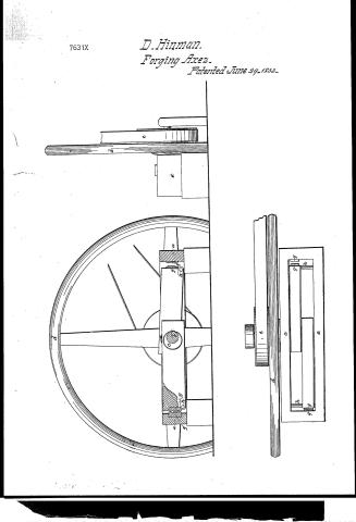
7631X
D. Hinman.
Forging Axes.
Patented June 29, 1833.
Page 2.
7631 X June 29, 1833 297
David Kinman of Canton, Co. of Hartford, Connecticut.
This schedule referred to in these Letters Patent & making part of the same, containing a description in the words of the said David Kinman himself of his improvement in machinery for forging axes.
So all to whom these presents shall come.
Be it known that I, David Kinman of Canton in the County of Hartford & State of Connecticut, have invented a new & useful Improvement in the Forging of all kinds of Axes, by driving or compressing the heated iron into dies or moulds of proper form by the application of mechanical pressure of a kind different or distinct from either rolling or hammering.
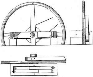
The said mechanical pressure may be given by many kinds of presses differently constructed, but having sufficient strength to accumulate & apply an intense pressure to the dies, in which the various parts of the work are to be formed. One of the dies being firmly fixed & stationary, the other die either forced against or towards it in a direct line, or, what I consider better, it may have a kind of rolling motion given to it at the same time that it is approaching the stationary die. A double press of sufficient strength & power, & the most convenient one that I have constructed is of the following description & dimensions viz. An oblong frame of cast Iron is laid horizontally and raised one or two feet above the level of the floor, the clear space within this frame, is about seven feet by two feet, the solid substance of this frame is about six inches thick by one foot deep. Across this frame the narrowest way is a large cast or wrought Iron shaft two inches diameter, on which are two cams or eccentrics so constructed as that both of the cams operate to move a slide between the sides of the frame — the eccentricity of the cams being such as to move said slide from one to two inches endwise during each revolution of said shaft — This shaft has a fly wheel upon it about sixteen feet diameter & weighing about six thousand pounds, & motion is given to it by a large belt in the end of the slide farthest from the shaft is a large motion rack fit into
Page 3.
which any form of dies may be set, such as the several parts of the work to be done may require), the corresponding stationary dies, being set in a bed or socket in the outer end of the iron frame. The same shaft & cams may work two profiles one on each side, between the shaft and each end of the frame. In order to give a kind of rolling motion to the slide (of course to the moving dies) it is not confined within rails or ribbons, but is sustained within the frame by a guide or passing thru said slide horizontally, very near the end, where the dies are set into it, & as near as may be in a line with the face of the dies, which are made a little conical or cylindrical that as the face of the moving dies may have a partially rolling motion as they approach the stationary dies. The other end of the slide on which the cams operate, being moved by the cams partly enwise & partly in a diagonal direction, or moved thru a segment of the circle which the cams describe.
What I claim as new, & as my own invention or improvement & for which I claim an exclusive privilege, is the application of a powerful press of the above or any of the more common constructions, operating on dies, moulds, or wedges, in a direct or nearly direct manner, to give to the heated iron & steel the several forms which are successively requisite in forging it into all kinds of steel.
Witnesses
Erastus Shaw
Isaac Kellogg
David Kinman
(700 words)
Patented 29th June 1832.
Published accounts: journal notice
Notice in the monthly list of patents, with remarks
Journal of the Franklin Institute, new ser., vol. 12 (1833), p. 401 · View the page
19. For Machinery for Forging Axes; David Hinman, Canton, Hartford county, Connecticut, June 29.
Remarks. Although this is termed a machine for forging axes, there is not a word in the description of it which applies any more to this particular business, than it would to a hundred others. The machine described is to act as a powerful press, which is to be used to force the heated metal into the proper form by placing it between dies. A particular press is described, but this is only given as one which the patentee approves, and he expressly says that a powerful press of any of the common constructions may be employed. He claims "the application of a powerful press of the above or any of the more common constructions, operating on dies, moulds, or swages, in a direct, or nearly direct, manner, to give to the heated iron and steel the several forms which are successively requisite in forging it into all kinds of axes." We have uniformly maintained the opinion that a patent cannot be sustained for the mere application of a well known process, or machine, to the making of a new article. If a machine must undergo some particular modification to enable it to perform a new process, or if there is any thing peculiar in the mode of operating with it, there is then invention, and of course novelty, but not otherwise.
DATAMP: illustration
Illustrations from DATAMP

DATAMP (Directory of American Tool and Machinery Patents), via the Internet Archive · Archived DATAMP page
About this record
- Patentee
- DATAMP
- Date
- DATAMP, USPTO records, Burke's List of Patents (1847)
- Invention
- DATAMP
- Listed in
- the Name and Date index of patents, DATAMP, USPTO records, Jim Shaw's X-patent list, the Journal of the Franklin Institute, Burke's List of Patents (1847)
- The sources give different dates; the date shown is the one most of them agree on.
- The National Archives' catalog gives the name differently.
- The Franklin Institute's journal confirms the date shown.
- Burke's 1847 Patent Office list gives the same patent.