

Drawings and documents
National Archives restored drawings: drawing
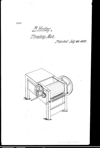
Benjamin Hinckley's Patent Drawing for a Thrashing Machine

National Archives, Restored Patent Drawings (Record Group 241) · Full-size scan at the National Archives · Catalog record
Show the text on the drawing Hide (36 words)
Words on the drawing as machine-read by the National Archives; not checked. Useful mainly for searching.
Entered / 130. THRASHING. / Thrashing Machines. / A. Cylinder Machines. / pr / BENJAMIN HINKLEY'S / CLASSIFICATION / Thrashing Machine / 7682-X / DIVISION. / Patented 23d July 1833. / OIR
USPTO scan
The patent as scanned by the USPTO
-
 Page 1
-
 Page 2
-
 Page 3


U.S. Patent and Trademark Office · Google Patents
Show the transcription Hide (672 words)
Machine transcription (LightOnOCR) of the pages as scanned by the USPTO, most of them the handwritten copies made when the records were restored after the 1836 fire. Not checked; it can misread handwriting, so compare it with the scan.
Page 1.
7682X
B. Hinkley,
Threshing Mach.
Patented July 23, 1833.
Page 2.
7/23/1833 7682X
July 23, 1833
Benjamin Franklin
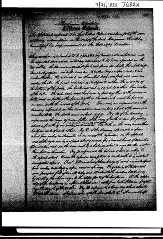
The Schedule referred to in their Letters Patent & making part of the same containing a description in the words of the said Benjamin Franklin himself of his improvement in the threshing Machine.
This machine is intended to be operated by hand or steam power, and the size and dimensions will vary according to its being operated on the two wheels. The dimensions suitable for hand power are: feet, three feet high, three inches square. Rails for ends are 18 inches long, one foot wide & two inches thick. The side rails are three feet long, one foot wide and two inches thick. The front end rail is designed to within three inches of the bottom of the feet. The back end rail is raised to within three inches of the top. The side rails and the frame is put together with various bolts, and in putting the frame together, the side rails must be formed in soon with the inside of the feet. These rails are represented on the drawing referred to in this description and making a part of the same, are marked C.C. The feet are marked g.g.g. Fig A of the drawing represents the large cylinder fitted with rows of teeth or wire projecting about a fourth of an inch in diameter. The teeth in the rows are within half an inch of each other. Fig C of the drawing represents a spout wheel four inches in diameter on one end of the cylinder, on the opposite end of the cylinder is a spout wheel geared for a round hand of diameter four inches, and on the same end is a balance wheel to regulate the motion three feet in diameter. Fig B represents the balance wheel and Fig C, the spout wheel. Under the cylinder and fitted to work with it is a sheet iron grate or apron. First I place a bed of three pieces of wood nine feet apart four inches wide laying upon wooden springs. The grate is of thick sheet iron punched full of small holes and attached to the wooden bed pieces by riveting the upper edges to the upper parts of the bed pieces. At the upper edge of the bed pieces is a piece of sheet iron with four teeth filed in, projecting the length of the teeth. Fig 22 represents a large cog wheel which drives the apron, which meshes into the gear wheel C. An iron shaft
Page 3.
7682x
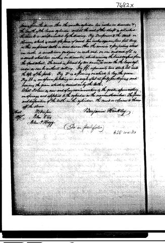
from the straw. Into the smaller cylinder two inches in diameter & the length of the larger cylinder, and at the end of the shaft is attached the comb or cleaner, which is made of pieces of wood two inches square, two feet long, in the upper end teeth or wires driven into the annulus & projecting about one inch, a small iron quillgun in each end, on one and one of it is a small wheel two inches in diameter, which raises the band caught from the speed wheel. The comb is placed by two arms, as near the the larger cyl. ends as can be without cutting. Fig ff. represents two studs, let into the top of the frame. Fig F is a flooring on which to lay the grain. Fig H is an apron pivoting in an angle of about forty-five degrees and receives the grain which is carried in by the teeth.
What I claim as new and of my own invention is the grate apron acting on springs and applied to the cylinder in the manner described. The form and disposition of the teeth in the cylinder, the comb or cleaner to throw off the straw.
Benjamin Hinkley
658 words
(Do in folio)
Published accounts: journal notice
Notice in the monthly list of patents, with remarks
Journal of the Franklin Institute, new ser., vol. 13 (1834), p. 36 · View the page
The teeth in the cylinder are to be of wire, about one-eighth of an inch in diameter, to project out about one-fourth of an inch, and to be one-half an inch apart; this constitutes "their form and disposition." The comb is a revolving piece of wood, two inches square, having teeth in it like rake teeth. 26. For a Washing Machine; Benjamin Hinkley, Fayette, Kennebeck county, Maine, July 28.
Remarks. Three wooden rollers, having their axes parallel to each other, are to be fixed across a trough. The middle cylinder, round which the clothes are to be wound, is to be ten inches in diameter, and to be turned by a crank; the others, four inches in diameter, are to be pressed up against the middle cylinder; the crank is to be turned alternately back and forth: The claim is to these cylinders lying horizontally. If the claim in this and the preceding patent should be found to stand the test of a fair investigation, we are no judge of likenesses; to us it appears that the things claimed resemble so closely what has been already placed in a similar predicament, as to require very nice eye to discriminate between them.
About this record
- Patentee
- DATAMP
- Date
- the Name and Date index of patents, DATAMP, USPTO records
- Invention
- DATAMP
- Listed in
- the Name and Date index of patents, DATAMP, USPTO records, the Journal of the Franklin Institute, Burke's List of Patents (1847)
- The Franklin Institute's journal spells the name differently.
- Burke's 1847 Patent Office list gives the same patent.