

Drawings and documents
National Archives restored drawings: drawing
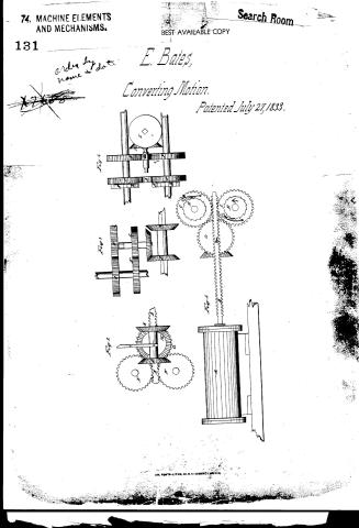
Elisha Bates' Patent Drawing for a Method of Applying Steam Power

National Archives, Restored Patent Drawings (Record Group 241) · Full-size scan at the National Archives · Catalog record
Show the text on the drawing Hide (120 words)
Words on the drawing as machine-read by the National Archives; not checked. Useful mainly for searching.
Novements / blisha Bates / 74. MACHINE ELEMENTS. / Racks and Pinions. / two / ACT / Applying Steam Power, / Patented the July 1833. / $4 / R&P / of / Saveral modification / CLASSI IC ATION / 7688 / DIV SION. / References, / Endine with Pearing'attached, / dearing / Fig.2. / Fif 3 / B. / Fight. / front / cytinder. B.pistenrod. / coq wheels with dogsD. / liking on rag'u heelsE. / I. econd coo whee ariving / tird wheel H. bevel-icheel, / shaftof G .K. two beveliok / ig my nown, / Fig.4. / Patent the / direction of the / Mar " / E, / MaM undu the Crumisiona of Patents in co / with act of bougres 30 March 1837 / these / which / Que shined of be reverbed wheel G mach in / to / order atrole / itents
USPTO scan
The patent as scanned by the USPTO
-
 Page 1
-
 Page 2
-
 Page 3
-
 Page 4
-
 Page 5
-
 Page 6


U.S. Patent and Trademark Office · Google Patents
Show the transcription Hide (1,655 words)
Machine transcription (LightOnOCR) of the pages as scanned by the USPTO, most of them the handwritten copies made when the records were restored after the 1836 fire. Not checked; it can misread handwriting, so compare it with the scan.
Page 1.
74. MACHINE ELEMENTS AND MECHANISMS.
131
Search Room
BEST AVAILABLE COPY
E. Bates,
Converting Motion.
Patented July 27, 1833.
Fig. 1
Fig. 2
Fig. 3
Fig. 4
AM. PHOTO-LITHO. CO. N. Y. (OSBORNE'S PROCESS)
Page 2.
Elisha Bates.
Letters Patent.
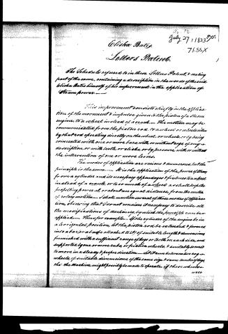
The Schedule referred to in these Letters Patent, & making part of the same, containing a description in the words of the said Elisha Bates himself of his improvement in the application of Steam power.
This improvement consists chiefly in the application of the movement & impulse given to the piston of a steam engine, to a wheel instead of a crank. The motion may be communicated from the piston rod to a wheel or wheels either by that rod operating directly on the wheel, or wheels, or by being connected with one or more bars, with, or without cogs, of any description, or with teeth, or creaks, or by pressure with or without the intervention of one or more levers.
The modes of application are various & numerous, but the principle is the same. It is the application of the power of steam from a cylinder and its necessary appendages & fixtures to a wheel instead of a crank, or to so much of a wheel as shall keep the propelling power at, or about an equal distance, from the center of rotary motion. I shall mention several of these modes of application, observing that I do not consider it necessary to describe all the modifications of machinery, by which the principle can be applied. Thus for example—If the cylinder of the engine be in a horizontal position, let the piston rod be extended & formed into a bar (or a bar be attached to it) of suitable length & dimensions, furnished with a sufficient range of cogs or teeth on each side, and supported by one or more hubs, or friction wheels, & suitably secured to move in a steady & proper direction. Let it run between two cog wheels, of suitable dimensions, of the same size & same number of cogs, then the machine might possibly be made to operate, if these wheels
Page 3.
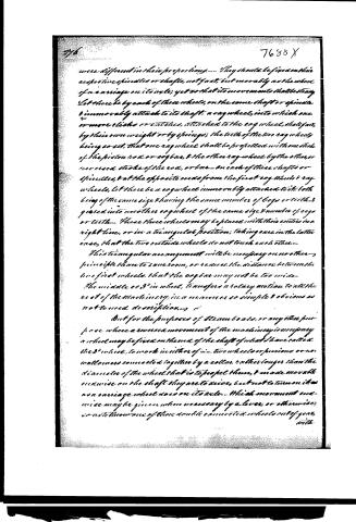
were different in their proportions. They should be fixed on their respective spindles or shafts, not fast, but movably as the wheel of a carriage on its axle; yet so that its movement shall be steady. Let there be by each of these wheels, on the same shaft or spindle, immovably attached to its shaft, a rag wheel, into which one or more clicks or catches, attached to the cog wheel, shall fall, by their own weight or by springs; the teeth of the two rag wheels being so set, that one rag wheel shall be propelled with one stroke of the piston rod or cog bar, & the other rag wheel by the other, or reversed stroke of the rod, or bar. On each of these shafts or spindles, & at the opposite ends from the first cog wheels & rag wheels, let there be a cog wheel immovably attached to it both being of the same size & having the same number of cogs or teeth, & geared into another cog wheel of the same size & number of cogs or teeth. These three wheels may be placed with their centres in a right line, or in a triangular position; taking care in the latter case, that the two outside wheels do not touch each other.
This triangular arrangement will be necessary on no other principle than to save room, or reduce the distance between the two first wheels, that the cog bar may not be too wide.
The middle or 3rd wheel, transfers a rotary motion to all the rest of the machinery, in a manner so simple & obvious as not to need description.
But for the purposes of Steam boats, or any other purpose where a reverse movement of the machinery is necessary, a wheel may be fixed on the end of the shaft of what I have called the 3rd wheel, to work in either of the two wheels or pinions or no, which are connected together by a collar, rather longer than the diameter of the wheel that is to propel them, & made movable on the shaft they are to drive, but not to turn on it as a carriage wheel does on its axle. Which movement and wise may be given when necessary by a lever, or otherwise, so as to throw one of their double connected wheels out of gear, with
Page 4.
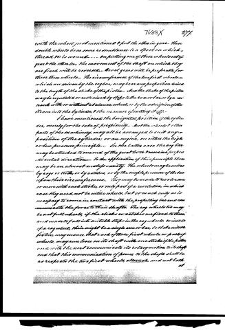
with the wheel just mentioned & put the other in gear. These double wheels bear some resemblance to a spool on which, thread is wound. On pulling one of these wheels out of gear the other is, the movement of the shaft on which they are fixed will be reversed. Bevel gears will be preferable for these three wheels. The circumference of the two first wheels, which are driven by the cogbar, may bear any proportion desired to the length of the stroke of the piston. And the stroke of the piston may be regulated or restrained by stops to the rod or bar, or by a crank with or without a balance wheel, or by the admission of the steam into the cylinder, & the manner of cutting it off.
I have mentioned the horizontal position of the cylinder, merely for the sake of perspicuity. But the wheels & other parts of the machinery, may all be arranged to suit any position of the cylinder; or an engine, on either the high or low pressure principle. In the latter case the cogbar may be attached to one end of the great lever & move in perpendicular direction. To the application of this principle there may be an almost endless variety. The wheels may be moved by cogs or teeth, or by catches, or by the simple pressure of the bar upon their circumferences. They may be made to revolve once or more with each stroke, or only part of a revolution, in which case they need not be entire wheels, but so much only as is necessary to come in contact with the propelling bar and communicate the force to their shafts. The cog wheels too may be not full wheels, if the cogs or catches are fixed to them, and made to fall into suitable steps in the cog wheels, or instead of a cog wheel, there might be a single arm or bar, so that a suitable fixture may ensure that each of these first wheels, or parts of wheels, may run loose on its shaft with one stroke of the piston and with the next communicate its rotary motion to its shaft and that this communication of power to the shafts shall be as respects the two first wheels, alternate, and not both at
Page 5.
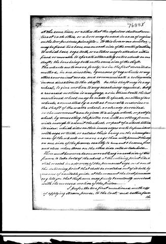
at the same time, or rather that the impulses shall not counteract each other, or a lever may be used in case of engines on the low pressure principle. To this lever or one similar, may be fixed two bars, one on each side of the center of motion, to which bars, cogs, teeth, or catches may be attached either fixed or movable to operate alternately on two wheels on one shaft, the bars being both on the same side of the shaft. The wheels are to move freely (as in the first described method, in one direction, by means of key wheels, or any other convenient mode, and communicate a rotary motion in one direction to the shaft. On this shaft may be a key wheel, to give motion to any machinery required. But if a reversed motion is necessary, as in steam boats, the last mentioned wheel may be made to operate, on either of two wheels, connected by a collar & movable endwise on the shaft of the water wheel, as already described.
or the movement can be given to a single wheel, or part of a wheel, by connecting the piston rod with an oblong frame, wide enough to admit the wheel, or part of a wheel between its sides; which sides on their inner edges are to be furnished with cogs, or teeth, or catches their being on the circumference of the wheels no more cogs than will permit the cog on one side of the frame, exactly to run out & become free and clear when those on the other side enter or take hold.
There must however be one movable cog on each side of the frame to take hold of the wheel at the entering point like a click or catch in a degree of the permanent cogs, and one at the delivering point that shall be snatched out of its hold, by means of a suitable guide, at the moment the last permanent cog lets go—that the frame may freely & constantly move back with the reversed motion of the piston.
I prefer the two first mentioned methods of applying steam power, to the last, and rather favor the
Page 6.
7688X
The opinion, that it will be more advantageous to make the two first wheels which are propelled by the piston rod, or cog bar so small as to revolve once, by each stroke of the piston, and possibly they might be made to revolve to advantage even more than once to a stroke. It will save machinery, power and expense to have them small (but not too small, & the velocity of the last wheels or moving parts of the machinery can be regulated or fixed by gearing.
Mount Pleasant, Jefferson County Ohio 5th 23rd 1833
Witnesses
Ochilee Harris
Helen L. Davis
Olivia Daley
1750 min
Published accounts: journal notice
Notice in the monthly list of patents, with remarks
Journal of the Franklin Institute, new ser., vol. 13 (1834), p. 39 · View the page
32. For a Mode of Applying Steam Power; Elisha Bates, Mount Pleasant, Jefferson county, Ohio, July 27.
Remarks. This patent is taken for a new principle of which we are told that modes of the applications are various and numerous. "It is the application of the power of steam from a cylinder and its necessary appendages and fixtures, to a wheel, instead of a crank." Several of the various modes of application are given in the specification, and one of them is represented in the drawing. In this, the piston carries a rod furnished with cogs on both sides of it, each side taking into a cog wheel, having rachet wheels so geared to it that they may carry a fly wheel in the same direction by the up and the down stroke of the piston. To the experienced machinist, we need say no more to convince him of the antiquity and inutility of the whole affair. We could fill many pages with what we know of similar attempts; but those who do not read would not buy it, and those who do have no need of it. For ourselves we seek no further to ascertain the utility of an improvement in the reciprocating engine, after we learn that it is intended to dispense with the crank motion; a motion upon which its useful operation is almost entirely dependent.
About this record
- Patentee
- DATAMP
- Date
- the Name and Date index of patents, DATAMP, USPTO records
- Invention
- DATAMP
- Listed in
- the Name and Date index of patents, DATAMP, USPTO records, Jim Shaw's X-patent list, the Journal of the Franklin Institute, Burke's List of Patents (1847)
- Burke's 1847 Patent Office list gives the same patent.