

Drawings and documents
National Archives restored drawings: drawing
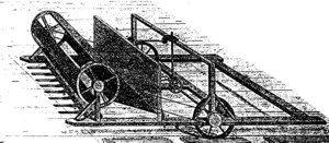
W. and T. Schnebly's Patent Drawing for a Machine for Cutting Grain, etc.

National Archives, Restored Patent Drawings (Record Group 241) · Full-size scan at the National Archives · Catalog record
Show the text on the drawing Hide (98 words)
Words on the drawing as machine-read by the National Archives; not checked. Useful mainly for searching.
Eintered / CLASSLATIATION / 7724-X DIVISION. / W.S T. SCHNEBLY / Cutting Grain,Grapbe / A. Frame / B. Cross-peices / Patented 22d aug 1833. / C. Perpendicular shaft / D. Shears / E. Revolving plane or sheet movingupon Rollers / F. Reel / G. Guard-board / H. Cap or Headblock / K. Long-handles diving molton to shears / Z. Front Roller / M. Coj segment / N Horizoniat-Shaft / 0. Pulleyon D-8 strap conneeled with Pulley a / P. Spur wheelon D° / Q. Pulley 072 Rollers which more Revolving Plane / PI / Made under the / with ach of 3"Mo / G. Strickland Delh
USPTO scan
The patent as scanned by the USPTO
-
 Page 1
-
 Page 2
-
 Page 3
-
 Page 4
-
 Page 5
-
 Page 6
-
 Page 7


U.S. Patent and Trademark Office · Google Patents
Show the transcription Hide (2,187 words)
Machine transcription (LightOnOCR) of the pages as scanned by the USPTO, most of them the handwritten copies made when the records were restored after the 1836 fire. Not checked; it can misread handwriting, so compare it with the scan.
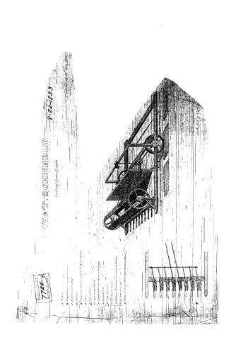
Page 1.
W. G. T. SCHNEEBILLY 8-22-1833
Cutting Grain Gaps
A. Frame
B. Engine
C. Propeller
D. Sides
E. Connecting Rods or Shafts
F. Tires
G. Axles
H. Cogs or Wheels
I. Teeth
J. Gears
K. Pulleys
L. Belts
M. Chains
N. Shafts
O. Bearings
P. Axles
Q. Wheels
R. Gears
S. Pulleys
T. Belts
U. Chains
V. Shafts
W. Bearings
X. Axles
Y. Wheels
Z. Gears
Filed April 29, 1833
C. M. B. 1833
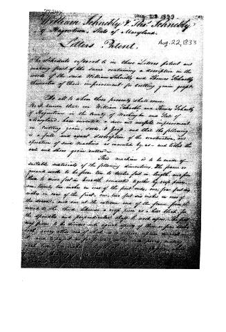
Page 2.
7724Y
William Schenckly & Thos. Schenckly
of Hagerstown, State of Maryland.
Letters Patent.
Aug. 22, 1833
The Schedule referred to in these Letters patent and making part of the same containing a description in the words of the said William Schenckly and Thomas Schenckly themselves of their improvement for cutting grain grass.
To all to whom these presents shall come
Be it known that we William Schenckly and Thomas Schenckly of Hagerstown in the County of Washington and State of Maryland, have invented a new and useful improvement in cutting grain, seeds, & grass, and that the following is a full and exact description of the construction, and operation of said machine as invented by us — and titled the reel and shear grain cutter.
This machine is to be made of suitable materials of the following dimensions. The frame or ground work to be from ten to twelve feet in length, and from three to nine feet in breadth connected together by cross pieces, one, twenty two inches in rear of the front ends, one, four feet six inches in rear of the first, one, two feet six inches in rear of the second, and one at the extreme end of the frame from the second to the third, likewise a cross piece as a base block for the spindle and perpendicular shaft to work upon. The first cross piece to be divided into equal spaces of three or four inches each, every other one of which is to receive a piece turned on its side to project as far forward as the cross pieces, making each twenty-two inches in length along of the cross pieces, which from the bearing of the spindle is not to pass under the cross pieces to extend the grain to the maximum of power of the
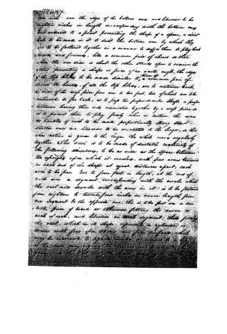
Page 3.
are inch one the edge of the bottom one and likewise to be eighteen inches in length corresponding with the bottom one but extended to a point presenting the shape of a span, a rivet hole to be made in it to suit the bottom one by which they are to be fastened together in a manner to suffer them to play back wards and forwards, like a common pair of shears so that when the one side is shut the other stands open to receive the arms presenting a shape or force of an acute angle, the edges of the top blades to be made similar to those of a common pair of shears the handles, if all the top blades, are to continue back, in view of the crop piece from one to two feet, two of which are to be continued so far back, as to lap the perpendicular shaft, a proper distance having their ends connected together by a crop piece so as to permit them to play freely when in motion, the arms or handles of each to be made proportionally strong that shorter ones are likewise to be connected to the longer, so that when motion is given to the longer the whole move regularly together, The reel is to be made of suitable materials of the following dimensions, to be as wide as the space between the uprights upon which it revolves, with four arms termed in each end of the shaft, at equal distances apart, each arm to be from two to four feet in length, at the end of each arm a segment corresponding with the circle which the reel will describe with the arms in it) is to be fastened from eighteen to twenty-four inches in curve length from one segment to the opposite one, this is to be put on a suitable piece of board or otherwise fitting the curve or arch of reel, and likewise on each segment, there forming the reel, which in its shape represents a cylinder or drum with four open sides and four surfaces which may be increased to any number, as occasion to a life, as the case may require the spares are to attach the gears into the reel and the lower edge of the reel
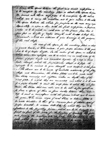
Page 4.
or braces. The space between the first and second crop pieces is to be occupied by the revolving plain or sheet. The space between the second and third crop pieces to be occupied by the wheels, which are to carry the machine, and to give motion to the whole. The space behind the wheels, for purposes as the case may require immediately or upon a line with the first crop piece, a perpendicular is to be raised on each side of the frame from two to four feet in height, of proper strength, with braces to keep them permanent, which are intended to give bearings to the guides of the reel shaft.
In rear of the space for the revolving plain or sheet a guard board, is to be raised, to give proper direction to the grain and to be of proper height, in the center of the space, in which the wheels move, two uprights are to be raised, one on each side of the frame, of proper height and connected together, by a cap or head block, through which the perpendicular shaft is to pass. The uprights to be raised to give strength and support to the frame.
The shears are to be made of suitable materials, of the following shape and dimensions, the bottom plates are to be made with two blades running out eighteen inches in length, clear of the rivet plate, to which they are connected and which is to be made of a proper breadth, to suit the crop piece to which they are fastened, the blades that run out, are to be set so far apart as to have a space of three or four inches between them, more or less to suit or correspond with the spaces which are to receive the grain. The inner edges of each blade or bottom plates to be made similar to that of a common pair of shears, and of proper breadth, to receive bolt holes, by which they are to be fastened to the projecting pieces, which are to be brought to a point in front of the plates, for the purpose of guiding the grain and passing the machine into its frame. The top blade or the part, which forms the double shears is to be made wide enough below or at the base to project its edge an inch or
Page 5.
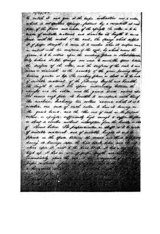
to catch it and give it the proper inclination over a roller which is set opposite springs, fastened by a screwbolt at each side of the frame and inside of the uprights. The roller is to be made of suitable material and diameter its length to correspond with the width of the reel, the springs which support it of proper strength, to cause it to revolve when its surface comes in contact with the surfaces of the reel, by which means the grains, is to be rolled upon the revolving plane or sheet immediately behind it. The springs are used to cause the space between the surface of the roller, and the surfaces of the reel to increase or diminish as the quantity of the grain passing through becomes greater or less. The revolving plane or sheet is to be made of suitable material of the following length and breadth. Its length to suit the space intervening between the upright and the roller and the guard board, varies upon the several sizes given its breadth to correspond with that of the machine, including two rollers around which it is to revolve, one end of each roller to have its bearing on the guard board, and the other end of each in the perpendicular rollers, or uprights, sufficiently high enough to suffer the plane or sheet to revolve without interruption from the heads, or ends of sheets below. The perpendicular or shaft is to be made of suitable material and of suitable length it is to be placed in the space between the boards and their supports having its bearings upon the head block, below, and the top above upon it, next to the head block, it has a top shaft, high up, it has an arm of proper length and construction immediately above the cap, it has a segment of a circle of proper material, from the foregoing cap to the guard board a horizontal shaft is then of suitable length and arranged in at right angles with the perpendicular at the top of it a gear wheel, with the one next to the cap, and another at back what, next to the guard board, and the latter of
Page 6.
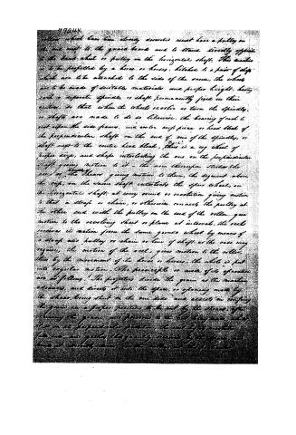
roller which has been already described must have a pulley on the one next to the guard board and to stand directly opposite to the hand wheel or pulley on the horizontal shaft. This motion is to be perfected by a horse or horses, hitched to a pair of steps which are to be attached to the side of the same, the wheels are to be made of suitable materials and proper height, having each a separate spindle or shaft permanently fixed in their centres, so that when the wheels revolve or turn the spindles, or shafts are made to do so likewise, the bearing of each to rest upon the side frame, and enter opposite or head block of the perpendicular shaft on the end of one of the spindles, or shaft next to the center head block, there is a cog wheel of proper size, and shape interlocking the one on the perpendicular shaft giving motion to it—the arm thereupon strikes the end of the shear giving motion to them, the segment above the cog, on the same shaft interlocks the spur wheel, on the horizontal shaft: at every round or revolution giving motion is that a strap or chain, or otherwise, connects the pulley at the other end with the pulley on the end of the roller, gives motion to the revolving sheet or plane at intervals, the reel receives its motion from the same grounds wheel by means of a strap also, pulley or chain or line of shaft as the case may require, the motion of the reel, gives motion to the roller, then by the movement of the horse or horses, the whole is put into regular motion. The principle or mode of its operation are as follows: The projections divide the grain as the machine advances, and direct it into the space, or opening made by the shear, being shut on the one side, and assists in confining the grain in a proper position to be cut by the shear, after receiving the grain, and previous to the last being made, when it is in its perpendicular position, the end of its revolution, the ends are gathered, the quantity measured by the space, and hence it is wholly done, and the roller, and the projection
Page 7.
1776. 407
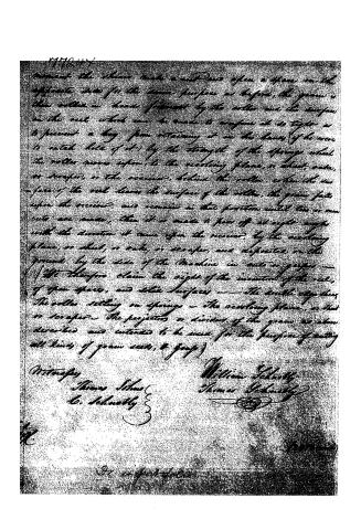
invent the above, made a cut-out space upon a plane on the opposite side for the same purpose as before, the grain is then rolled in loose form, by the roller over the surface on the reel, which can be made to conform it as tight as to prevent a bag from retaining it in the leaves (if he were to catch hold of it) by the strength of the springs which the roller moves upon, to the revolving plane, or sheet, rake, or scraper, or the receiver, behind the roller, when the surface of the reel leaves the surface of the roller, the grain falls upon the receiver, and remains in that position until two or more cuts are made, then it is made to pass off at right angles with the direction it came upon the receiver, by the revolving plane, or sheet, or rake, or scraper, and deposited on the ground by the side of the Machine in cuts or grooves — We therefore claim the right of the invention of the reel, of open spaces, and solid surfaces — the double edges, the roller setting on springs — the revolving plane, or sheet or scraper — the projector or divider of the grain as above described are intended to be used for the purpose of cutting all kinds of grain seeds, & grass)
Witnesses
Thomas Schney
W. Schney
William Schney
Thomas Schney
Filed April 1876
91 in front of the
DATAMP: illustration
Illustrations from DATAMP

DATAMP (Directory of American Tool and Machinery Patents), via the Internet Archive · Archived DATAMP page
About this record
- Patentee
- DATAMP
- Date
- the Name and Date index of patents, DATAMP, USPTO records
- Invention
- DATAMP
- Listed in
- the Name and Date index of patents, DATAMP, USPTO records, Jim Shaw's X-patent list, Burke's List of Patents (1847)
- Burke's 1847 Patent Office list gives the same patent.