

Drawings and documents
National Archives restored drawings: drawing
J. Atwater's Patent Drawing for a Combination Stove


National Archives, Restored Patent Drawings (Record Group 241) · Full-size scan at the National Archives · Catalog record
Show the text on the drawing Hide (69 words)
Words on the drawing as machine-read by the National Archives; not checked. Useful mainly for searching.
Sheet 1. 126 STOVES & FU RNACES / It / 751154] Heating Stoves. / $350 / J. ATWATER'S / 3-shat lost / Combination Stove. / CLASSIFICATION / Patented August 23ed 1833 / 7725-X / DIV ISION. / VHP 219 / Tig:1. / "4
Sheet 2. R' / Atwater, / Heating Stove / CLASSI ION / Patented Aug 23 1833 / DIVISION. / Fig. 11. / Fig. IV. / Fig. III. / d.d. / 10 of I n / £.6. / f.5. / f.3. / f,4, / 0m / 112 / f.1. / f.2. / O/A
USPTO scan
The patent as scanned by the USPTO
-
 Page 1
-
 Page 2
-
 Page 3
-
 Page 4
-
 Page 5
-
 Page 6
-
 Page 7
-
 Page 8
-
 Page 9


U.S. Patent and Trademark Office · Google Patents
Show the transcription Hide (2,421 words)
Machine transcription (LightOnOCR) of the pages as scanned by the USPTO, most of them the handwritten copies made when the records were restored after the 1836 fire. Not checked; it can misread handwriting, so compare it with the scan.
Page 1.
7725X
Sheet 1-3 Sheets.
J. Atwater.
Heating Store.
Patented Aug. 23, 1833.
Fig. 1.

Page 2.
7725X
J. Atwater.
Heating Stove.
Patented Aug. 23, 1883.
Sheet 2-3 Sheets.
Fig. 2.
Fig. 4.
Fig. 3.
Page 3.
7725X
J. Atwater.
Heating Stove.
Patented Aug. 23, 1833.
Sheet 3-3 Sheets.
Fig. 7.
Fig. 8.
Fig. 9.
Fig's. 5 and 6 unavailable.
Page 4.
Aug. 23, 1833
James Alwater
Letters Patent
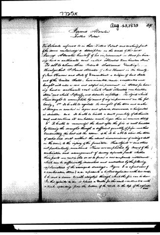
The above reference is to the Letters Patent and making part of the same containing a description in the words of the said James Alwater himself of his improvement in Stoves for burning hard or anthracite coal called "Alwater's Combination Stove." To all to whom these Presents shall come Greeting—
Know ye that I James Alwater of New Haven in the County of New Haven and State of Connecticut a Citizen of said State and of the United States—have invented, made, constructed and brought into use a new and useful improvement in Stoves for burning hard or anthracite coal which I call "Alwater's Combination Stove" and which I specify, and describe as follows—
The objects which I have sought to accomplish by means of my improvement are the following:
1. To be able to regulate the draught of the stove and make it stronger or weaker in degree and upward, downward, or horizontal in direction.
2. To be able to kindle a small quantity of anthracite coal and continue its combustion much longer than in common stoves.
3. To be able to economize the heat after the fire is well kindled by turning the draught through a sufficient quantity of pipe, and thus transmitting the heat into the room.
4. To be able to clear the stove of ashes and dust without the usual inconveniences of raising a dust in the room, to the injury of the furniture.
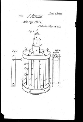
These objects & some others not particularly mentioned I have accomplished by means of the combination and arrangement of several separate parts, whether these parts are new or old so as to form a new compound instrument which can be sufficiently described and understood by the following explanations of the annexed drawings—Figure 1 is a front view of a combination stove; a.a. represents a hollow cylinder with two doors t.t. and a screen C with slings through which the fire can be seen. In this cylinder a.a. is placed a grate for the coal consisting with a back extending from the bottom of the grate to the top of the cylinder.
Page 5.
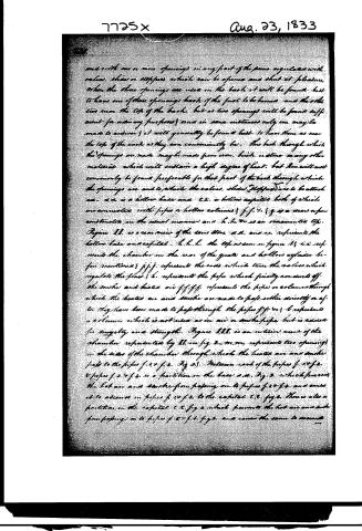
and with one or more openings in any part of the same regulated with valves, slides or stoppers which can be opened and shut at pleasure. When the three openings are used in the back it will be found best to have one of these openings back of the fuel to be burned and the other two near the top of the back, but as two openings will be found sufficient for ordinary purposes and in some instances only one may be made to answer it will generally be found best to have them as near the top of the back as they can conveniently be. The back through which the openings are made may be made from iron, brick or stone or any other materials which will sustain a high degree of heat, but iron will most commonly be found preferable for that part of the back through which the openings are and to which the valves, slides, stoppers are to be attached. a.d. is a hollow base and c.e. a hollow capital both of which are connected with pipes or hollow columns; f.f. v. & g is a draw or pan constructed in the usual manner and h.h. v. is an ornamented top. Figure 11. is a rear view of the same stove. a.d. and c.e. represents the hollow base and capital. h.h.h. the top as seen in figure 11; v.v. represents the chamber on the rear of the grate and hollow cylinder before mentioned; f.f.f. represents the rods which turn the valves which regulate the flow; h. represents the pipe which finally conducts off the smoke and heated air; f.f.f.f. represents the pipes or columns through which the heated air and smoke are made to pass either directly or after they have been made to pass through the pipes f.f. v.v.; l represents a column which is not used as an air or smoke pipe but is added for solidity and strength. Figure 12. is an interior view of the chamber represented by ll in fig 2. m.m. represents two openings in the sides of the chamber through which the heated air and smoke pass to the pipes f.1.v.f.2. fig 23. Between each of the pipes f.1.v.f.2. v pipes f.3. & f.4. is a partition on the base a.d. fig 2. which prevents the hot air and smoke from passing on to pipes f.3.v.f.4. and causes it to ascend in pipes f.1.v.f.2. to the capital c.e. fig 2. There is also a partition on the capital c.e. fig 2 which prevents the hot air and smoke from passing on to pipes f.5.v.f.6. fig 2. and causes the same to ascend on
Page 6.
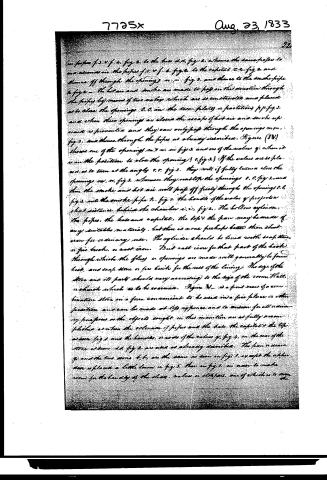
in pipes f. 5. v. f. 4. fig. 2. to the base d. d. fig. 2. whence the same pipes to an ascension in the pipes f. 5. v. f. 6. fig. 4. to the capital r. r. fig. 2. and thence off through the openings m. m. fig. 3. and thence to the smoke pipe h. fig. 2. The heat and smoke are made to pass on this direction through the pipes by means of two valves which are so constructed and placed as to close the openings o. o. in the iron plates or partitions p. p. fig. 3. and when these openings are closed the escape of hot air and smoke upwards is prevented and they can only pass through the openings m. m. fig. 3. and thence through the pipes as already described. Figure (IV) shows one of the openings m. m. in fig. 3. and one of the valves q. when it is in the position to close the opening o. o. fig. 3. If the valves are so placed as to turn at the angle r. r. fig. 3. they will if fully turned close the openings m. m. fig. 3. whereas they will open the openings o. o. fig. 3. and then the smoke and hot air will pass off freely through the openings o. o. fig. 3. into the smoke pipe h. fig. 2. The handle of the valve of projection shall exist behind the chamber a. a. fig. 2. The hollow cylinder, the pipes, the base and capital, the top and the pan may be made of any suitable material, but there is none perhaps better than sheet iron for ordinary use. The cylinder should be lined with soap stone, or fire brick, or cast iron. But cast iron for that part of the back through which the flues or openings are made will generally be found best, and soap stone or fire brick for the rest of the lining. The size of the stove and its parts should vary according to the size of the room, Hall, or church which is to be warmed. Figure V. is a front view of a combustion stove in a form convenient to be used in a fire place or other position and can be made at first appearance and to answer for all ordinary purposes as the objects sought in this invention are as fully accomplished as when the elevation of pipes and the base, the capital and the top as seen fig. 1 and the handles, or rods of the valves q. fig. 4. in the rear of the stove as seen in fig. 2 are used as already described. The pan or cover g. and the two doors h. k. are the same as seen in fig. 1 except the upper door is placed a little lower in fig. 5 than in fig. 1. in order to make room for the handle of the slides, valves or stoppers, one of which is to turn the
Page 7.
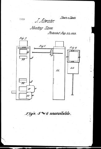
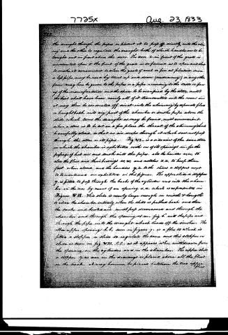
the draught through the pipes or permit it to pass off directly into the chimney and the other to regulate the draught both of which handles are to be brought out in front above the stove. The door, c, in front of the grate is represented as open & the front of the grate is so formed as to open and shut to make it convenient to clean the grate of coal or fire at pleasure. In one a life pipe may be used by turning up and down (see drawing) & in any other form may have been given to the pipes or a pipe according to the taste or fancy of the manufacturer and the space to be occupied by the stove until the heat shall have been nearly all of it transmitted into the room and it may then be conducted off direct into the chimney by separate flues or brought back into any part of the chamber or into the pipe above the slide which turns the draught as may be found most convenient. When a stove is to be set on a fire place the throat of the chimney should be carefully closed, so that no air escapes through it which does not pass through the stove or its pipes. Fig. IX. is a side view of the same stove in which the chamber is exhibited with one of its openings m, for the passage of hot air and smoke into the pipes. Also the handles m, m, to close the flues and their bearings w, w, and notches x, x, to keep them fast when closed and the handles y, z, to the slides or stoppers may be mentioned are exhibited in this figure. The upper slide or stopper y, is fitted to pass through the back of the cylinder and into the chamber in the rear by means of an opening u, u, which is represented in Figure VII. This slide is nearly large enough in width & length to close the chamber entirely when the slide is pushed back and then the smoke and heated air must pass downwards and through the chamber and through the opening at m, fig. 6, into the pipe and through the pipe into the draught which leads off the smoke. The other upper opening b, b, seen in figure 7, is a flue to which is fitted a stopper or slide to regulate the same and this stopper or slide is seen in fig. VIII. C, C, as it appears when withdrawn from the opening in the cylinder and in the chamber. The upper slide or stopper y, as seen in the drawings is placed above all the flues in the back. It may however be placed between the two upper flues.
Page 8.
7725X Aug. 23, 1833
22.
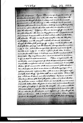
flow when so required. Figure 1X is a view of a horizontal section of the chamber as seen from above when the slide a.a. which turns the air and smoke through the pipes is drawn out so as to leave a direct communication into the chimney or other outlet for smoke and dust. The section of the chamber is constructed a little by means of the projections a.a. so as to keep the slide rests when it is pushed in and close the chamber. In figure 7, there are two doors ff, ff, near the bottom of the chamber, the lower one being placed as low as possible to make it convenient to remove ashes and dust which collect at the bottom of the chamber. The upper one can be used as a flue when the other flue is all stopped, and the draught will thus be turned downwardly through the bottom of the grate gg, gg, in fig. 7, denotes two flues in the back of the stove opening into the chamber already described and seen in fig. 5. l.l. which flues are regulated by valves and moved by the handles u.u. in fig. 6. a stand or frame for the stove to rest on and a pan for ashes & coal, to be placed near the stove in front will be found useful. They may be made from such materials & in such forms & size as shall be most convenient. I claim as my invention the combination and arrangement by which the separate parts are adapted to each other and formed into one compound instrument to accomplish the four objects enumerated at the commencement of this specification which separate parts so combined are the following (viz.) 1st a cylinder, prismatic or furnace stove with one or more openings in any part of the back thereof, regulated with one or more valves, slides or stoppers, which can be opened and shut at pleasure. 2d an air and dust chamber in the rear of the back of the grate or stove into which the flues open with two or more outlets for heat, air and smoke and one or more doors at the bottom below the grate to remove dust and ventilate the room and pipes if necessary to regulate the draught. 3d a set or collection of one or more pipes in any form, but so arranged as to be connected with the air chamber for the retention and diffusion of heat through the pipes into the room. 4th a set of one or more valves, slides or stoppers by which the draught is made to pass through the pipes of smoke or air.
Page 9.
Aug. 23, 1833
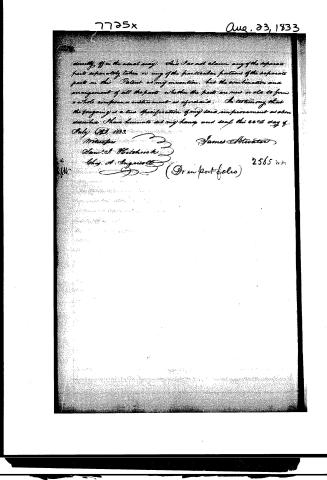
directly off in the usual way. This does not claim any of the separate parts separately taken or any of the particular features of the separate parts in this Patent as my invention, but the combination and arrangement of all the parts whether the parts are new or old to form a whole complete instrument as aforesaid. In testimony that the foregoing is a true specification of my said improvement as above described I have hereunto set my hand and seal this 22nd day of July A.D. 1833.
Witness
Sam'l C. Whitehead
Chas. A. Angerott
James Atwater
(Gran Portfolio)
2565
Published accounts: journal notice
Notice in the monthly list of patents, with remarks
Journal of the Franklin Institute, new ser., vol. 13 (1834), p. 118 · View the page
21. For a Stove for burning Anthracite, denominated the "Combination Stove;" James Atwater, New Haven, New Haven county, Connecticut, August 23.
Remarks. The objects which the patentee proposes to accomplish by means of this stove, he states to be, 1st, to be able to regulate the draft, and to direct it upwards, downwards, or horizontally. 2nd. The ability of employing a small quantity of coal, and to continue its combustion longer than usual. 3d. To economise heat by turning the draft through pipes, after the combustion has advanced, so as to diffuse it through the apartment. 4th, to clear the stove of ashes, without allowing it to escape into the room. This stove is too complex to allow of our attempting to give a clear idea of its various parts, to represent which, and the different modes of constructing it, the specification is accompanied by nine figures. The claims made are to the combination and arrangement of the several parts so adapted to each other as to accomplish the four purposes above proposed. The separate parts so combined, are said to be, 1st, a stove or furnace, either cylindrical or prismatic, having one or more openings in its back, furnished with valves, to open or close as required. 2nd, a chamber in the rear for air and dust, into which the flues open, and having outlets for heated air and smoke, and furnished also with doors below the grate, for the purpose of removing dust, ventilating the room, and regulating the draft. 3d, pipes connected with the air chamber, and intended to diffuse heat through the room. 4th, one or more valves, slides, or stoppers, to regulate the draft through the pipes. This enumeration is closed by a statement that the patentee does "not claim any of the separate parts separately taken, or any particular portions of the separate parts, but the combination and arrangement of all the parts, whether new or old, to form a whole compound instrument, as aforesaid." A claim of this description seems to require that the parts so combined should present an instrument distinctly characterized by their combination, and we have no doubt that such is the case with the stove before us in the estimation of the patentee; we, however, might be at a loss to tell in what particulars his rights would be violated, were any one to construct a stove varying in form from those given in the drawings; we presume, however, that the patentee will meet with numerous instances in which he will think that they are invaded.
About this record
- Patentee
- DATAMP
- Date
- the Name and Date index of patents, DATAMP, USPTO records
- Invention
- DATAMP
- Listed in
- the Name and Date index of patents, DATAMP, USPTO records, Jim Shaw's X-patent list, the Journal of the Franklin Institute, Burke's List of Patents (1847)
- Burke's 1847 Patent Office list gives the same patent.