

Drawings and documents
USPTO scan
The patent as scanned by the USPTO
-
 Page 1
-
 Page 2
-
 Page 3
-
 Page 4


U.S. Patent and Trademark Office · Google Patents
Show the transcription Hide (860 words)
Machine transcription (LightOnOCR) of the pages as scanned by the USPTO, most of them the handwritten copies made when the records were restored after the 1836 fire. Not checked; it can misread handwriting, so compare it with the scan.
Page 1.
7732X
S. King,
Making Stares,
Patented Aug. 29, 1833.
![Diagram of a mechanical device with labeled parts B, E, H, and others, showing a cylindrical structure with internal components and external arms.]
AM. PHOTO-LITHO. CO. N.Y. (OSBORNE'S PROCESS)
Page 2.
7732x Aug. 29, 1833
Summer King of Chittenango, New York,
Letters Patent.
The schedule referred to in these Letters Patent and making part of the same containing a description in the words of the said Summer King himself of his improvement in the saw for sawing staves and other cylindrical work.
To all to whom these presents shall come Greeting.
Be it known that I Summer King of Chittenango in the County of Madison and State of New York, have invented a new and useful improvement in a saw for sawing staves & other cylindrical work, and the following is a full and exact description of the construction and operation of the said saw as invented or improved by me.
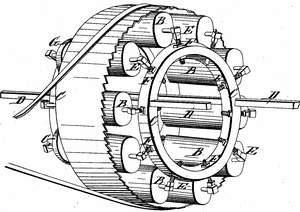
The saw to be in a cylindrical form the surface of the saw to be concave, convex, or flat, for the purpose of forming the bidge, or swell in the stave, or for giving a longitudinal curve to the work, or sawing it straight as the case may require, the saw to be supported and set of friction rollers or wheels, which are to be supported in the following manner. Two cylinders or rims made of cast iron or wood to be fastened by bars or cross pieces and at sufficient distance apart to admit the said friction rollers or wheels to play between them, the bars to run through and within the said rims and two of them to extend so far as to fasten the saw frame to any permanent part of the building or the frame upon which the whole machine rests. The cylinders or rims to have holes thru them perpendicular to the surface to receive posts, or standards to pass through them, which are to have each a head or block of metal or composition permanent or movable upon said posts or standards, with holes in them to receive the
Page 3.
quagons of the said friction rollers, and upon which the said friction rollers rest, and move. The said posts or standards to have a screw head set upon them, where they pass into the said cylinders or ovens with two nuts on each for the purpose of supporting raising or lowering the posts and setting the rollers to the saw, or to have longitudinal holes in the cage of the cylinders for the purpose, and receiving bolts to run through them, by which the posts or standards may be made fast, by a nut or screw, or raised or lowered at pleasure. The said friction rollers may also run upon pivots. One of the said rollers, or one or more of them to be set askew or making a small angle with the other rollers at the end towards the teeth of the saw, to incline the saw back against wheels which are fixed on axles for the purpose of preventing the saw from running off from the rollers. The axis of the last mentioned wheels to be fastened on the back cylinder with a screw in such manner as that they may be moved back and forward at pleasure. The saw being fixed upon the rollers a band or strap passes round it as round a drum except a sufficient space to admit the timber that is to be sawed to pass through the two sides of the band. Friction rollers are placed one above and one below the carriage that carry the timber to be sawed, to keep the band close to the saw. The top roller to be fastened by arms fastened to the cylinder, the other to the frame below. The timber to be sawed to be carried between the sides of the band where they leave the saw on a carriage. The band passing round the saw also, passes over a drum separate from the machine and propelled by any power. All the above mentioned wheels or rollers to be made of wood or metal or any kind of composition. It will require about ten friction rollers to support a saw two feet in diameter, which is the proper size for a barrel, and for other uses in proportion.
Page 4.
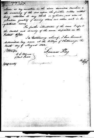
claim as my invention in the above described machine is the running of the saw upon the friction rollers without being attached to any block or cylinder, and also its peculiar quality of sawing staves and other work in longitudinal curves.
For further illustration of the same I refer to the model and drawing of the same deposited in the Patent Office.
In testimony whereof, I have hereunto subscribed my name at the Village of Chittwango, this tenth day of August 1833.
Witnesses:
G. G. Warner
Paul Sudd
Summer King
(949 made) (Drawing made)
64 M. 12
Published accounts: journal notice
Notice in the monthly list of patents, with remarks
Journal of the Franklin Institute, new ser., vol. 13 (1834), p. 121 · View the page
27. For a Saw for Sawing Staves and other Cylindrical Work; Sumner King, Chittenango, Madison county, New York, August 29.
Remarks. VOL. XIII.-No. 2.- FEBRUARY, 1834. 16 The saw in this case is to be a complete hoop, with teeth upon one of its edges. Its diameter must, of course, depend upon the curvature required in the stuff to be cut. The inside of the saw rests against friction rollers, placed in a circle, at equal distances apart, excepting at the point where the cutting is to be effected, a space being left there, equal in width to that of the stuff to be cut. A band is to be placed around the saw, and over a drum by which it is to be turned, and this band is made to embrace the saw around a large portion of its circumference by means of two friction pulleys, which, however, leave it free at the cutting part. Twoof the friction rollers are to have a cant, to incline the saw to keep back on its bearing, which is against friction rollers. The claim is to a sawing machine so constructed. We believe the plan to be new, but are apprehensive that the stiffness in the cutting part will not be sufficient to cause the saw to work well, without making it inconveniently thick.
DATAMP: illustration
Illustrations from DATAMP
DATAMP (Directory of American Tool and Machinery Patents), via the Internet Archive · Archived DATAMP page
About this record
- Patentee
- DATAMP
- Date
- the Name and Date index of patents, DATAMP, USPTO records
- Invention
- DATAMP
- Listed in
- the Name and Date index of patents, DATAMP, USPTO records, Jim Shaw's X-patent list, the Journal of the Franklin Institute, Burke's List of Patents (1847)
- Burke's 1847 Patent Office list gives the same patent.