

Drawings and documents
USPTO scan
The patent as scanned by the USPTO
-
 Page 1
-
 Page 2
-
 Page 3
-
 Page 4


U.S. Patent and Trademark Office · Google Patents
Show the transcription Hide (1,043 words)
Machine transcription (LightOnOCR) of the pages as scanned by the USPTO, most of them the handwritten copies made when the records were restored after the 1836 fire. Not checked; it can misread handwriting, so compare it with the scan.
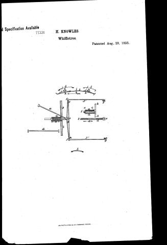
Page 1.
Specification Available
7733X
H. KNOWLES.
Whiffletree.
Patented Aug. 29, 1833.

AM. PHOTO-LITHO. CO. N.Y. (OSBORNE'S PROCESS).
Page 2.
8/29/1833 7733X
Aug. 29 1833 124
Hazard Principles of Colchester Commentant
Letter Patent
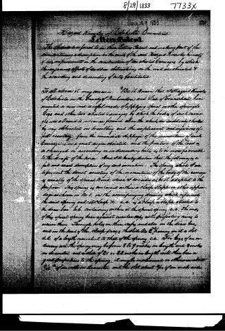
The Letters are referred to me then Letter Patent and making part of the same containing a description in the words of the said Hazard himself of his improvements in the construction of two wheeled Carriages by which the injurious effects of sudden obstructing on the road are obviated & the ascending and descending of hills facilitated.
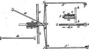
To all whom it may concern. I do it known that I Hazard Prince of Colchester in the County of Middlesex and State of Connecticut have invented a new and useful mode of applying spiral or other springs to Bogs and other two wheeled Carriages by which the bodies of such Carriages are allowed to advance forward when the wheels are suddenly checked by any obstruction in travelling and the unpleasant and injurious effects resulting from the immediate stoppage of the momentum of such Carriages is in a great degree obviated, and the position of the load is so changed in ascending or in descending hills as to be more favorable to the draft of the horse. And I do hereby declare that the following is a full and exact description of my said invention. The Spring which I use to prevent the direct arresting of the momentum of the body of the carriage is usually of the spiral kind which I consider as best adapted to the purpose. This spring is contained within a clamp staple or other apparatus as shown in No 1. in the accompanying drawing which represents the said spring and its clamp &c. a.a. is a clamp or staple attached to the draw-bar b.b. containing within it the spiral spring c.c. the ends of this spiral spring bear against circular cups with projecting rims to receive them. Through holes in these cups and also on the draw bar, and in the head of the clamp passes the slide No 2. having on it a slot d.d. of a length equivalent to that of the spring c.c. For bogs of an ordinary use the spring may be from 8 to 9 inches in length and 8 inches in diameter, and a slide of 21 or 22 inches in length will then have a good proportion to the spring. It may be made of iron or other material 3/4" of an inch in diameter and the slot about 3/4 of an inch wide.
Page 3.
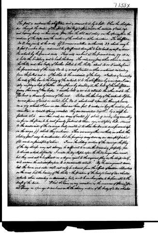
The part c embraces the whiffletree and is secured to it by a bolt. When the sleigh passes through the center of the spring, its legs or pins are on the outside of each cage and having heads on their ends, pass thru the slot and resting on the spring thru the medium of the cages, causes the motion of the vehicle in either direction. The whiffletree No. 3 has joints at the ends, ff, to receive metalties or other rods 3, 3, which may be 2 feet 9 inches long, and must be of sufficient strength to hold back as well as draw the vehicle by the forward cars. These rods are bent at the forward ends, gg, so as to hold the bristling and to hook the stonies. The rods may pass either above or under the thills and thru loops of leather bolted to the thills, about 4 or 5 inches from the forward ends of the rods. No. 4 is a rod of metal or other material extending from the forked end c, of the stile to the underside of the body. Instead of connecting the ends of this bar to the body of the vehicle & to the whiffletree by iron eyes, I usually employ a loop of leather, strengthened by doubling it, the bolt of the whiffletree passing thru one of these loops, & another bolt is used to attach the other end to the body. The load is drawn by means of this rod. Below the body of the vehicle I place two or three pieces of wood or metal, like No. 5, which rest upon the thoroughbraces, in a way which I have in use. There are three feet 2 inches in length and in form resemble a crook or spring mounted. They are connected together by a cross bar fastened at i, near their ends, on ways of metal jj, about 9 inches long ascending in from the pieces h, h and firmly fastened to them, eye, or stoles, k, k, secured to the underside of the carriage body enable it to slide backward and forward up on the ways jj, which they embrace. There are many other methods in which this sliding part may be constructed, but the foregoing may serve as an example of a novel idea, mode or principle of action. From the sliding motion of the carriage, the play of the log staple may not always be sufficient to render the bracing perfectly free to obviate which difficulty, I make the log staple upon the thills longer than usual; but they need not be lengthened in a degree equal to the required play as the staple itself will overcome the intended play to a considerable extent. By the arrangement described, the horse and rider will not only be relieved from the effects of sudden elevations on the road, but the bearing of the thills, the position of the body & load of the vehicle, when ascending or descending hills, will be so changed as to be favorable to the draft of the horse. What I claim as my invention is the manner of placing the spring or springs so combined with the sliding motion of the body of a two wheeled
Page 4.
7733X
125.
arrange as to produce the effects described; whether the separate parts be constructed exactly in the manner hereinbefore set forth, or in any other manner operating upon the same principle and producing the same effects.
Witnesses
A. O. Jones
S. Badger.
Hayard & Anocles.
(Or in portfolio)
1005 words.
146
Published accounts: journal notice
Notice in the monthly list of patents, with remarks
Journal of the Franklin Institute, new ser., vol. 13 (1834), p. 122 · View the page
28. For an improvement on Two wheeled Carriages; Hazard Knowles, Colchester, New London county, Connecticut, August 29.
Remarks. (See the specification.)
Published accounts: journal notice
Notice in the monthly list of patents, with remarks
Journal of the Franklin Institute, new ser., vol. 13 (1834), p. 123 · View the page
There is little of novelty in this combination, many analogous contrivances having been made; it seems to us, therefore, that the patentees must be confined to their own specified arrangement, as their stove does not possess any distinctive character, to point it out under any considerable change of form. No particular means are proposed for diffusing the heat from the air chamber, and we are very apprehensive that the patentees will find it less diffusible than they anticipate. SPECIFICATIONS OF AMERICAN PATENTS. Specification of a patent for applying spiral or other springs to gigs, and other two wheeled carriages. Granted to HAZARD KNOWLES, Colchester, New London county, Connecticut, August 29, 1833.
Remarks. To all whom it may concern, be it known, that I, Hazard Knowles, of Colchester, in the county of New London, and state of Connecticut, have invented a new and improved mode of applying spiral or other springs to gigs and other two wheeled carriages, by which the bodies of such carriages are allowed to advance forward when the wheels are suddenly checked by any obstruction in travelling, and the unpleasant and injurious effect resulting from the immediate stoppage of the momentum of such carriage, is in a great degree obviated, and the position of the load is so changed in ascending or descending hills as to be more favourable to the draft of the horse. And I do hereby declare that the following is a full and exact description of my said invention. The spring which I use to prevent the direct arresting of the momentum of the body of the carriage is usually of the spiral kind, which I consider as best adapted to the purpose. This spring is contained within a clasp staple, or other appendage, as shown in No. 1 in the accompanying drawing, which represents the said spring and its clasp, &c. aa is a clasp or staple, attached to the draw bar b b, containing within it the spiral spring c c. The ends of this spiral spring bear against circular caps, with projecting rims to receive them. Through holes in these caps, and also in the draw bar, and in the head of the clasp, passes a slide, No. 2, and having in it a slot, dd, of a length equivalent to that of the spring c c: For gigs of an ordinary size, the spring may be from eight to nine inches in length, and three inches in diameter; and a slide of twenty-one or twenty-two inches in length will then bear a good proportion to the spring. It may be made round, or otherwise, about three-fourths of an inch in diameter, and the slot about two-tenths of an inch wide. The parte embraces the whiffle tree, and is secured to it by a bolt. When the slide passes through the centre of the spring, two keys, or pins, one on the outside of each cap, and having heads on their ends, pass through the slot, and acting on the spring through the medium of the caps, eases the motion of the vehicle in either direction. The whiffletree, 3, has joints at the ends ff, to receive metallic or other rods, 3', 3', which may be two feet nine inches long, and must be of sufficient strength to hold back, as well as to draw the vehicle by the forward ends. These rods are bent at the forward ends g g, so as to hold the britching, and to hook the traces. The rods may pass either above or under the thills, and through loops of leather bolted to the thills, about four or five inches from the forward ends of the rods. No. 4, is a rod of metal, or other material, extending from the KNOWLES' Sliding Gig Springs. forked end e of the slide, to the under side of the body, Instead of connecting the ends of this bar to the body of the vehicle, and to the whiffletree by iron eyes, I usually employ a loop of leather, strengthened by doubling it: the bolt of the whiffletree passes through one of these loops, and another bolt is used to attach the other end to the body. The load is drawn by means of this rod. Below the body of the vehicle, I place curved pieces of wood or metal hh, No. 5, which rest upon the thorough braces. In a gig which I have in use, these are three feet two inches in length, and in form resemble a cradle spring inverted; they are connected together by a cross bar fastened at i. Near their ends are ways of metal jj, about nine inches long, resembling in form the pieces hh, and firmly fastened to them. Eyes, or staples kk, secured to the under side of the carriage body, enable it to slide backward and forward upon the ways jj, which they embrace. There are many other methods in which this sliding part may be constructed, but the foregoing will serve as an exemplification of its mode or principle of action.
DATAMP: illustration
Illustrations from DATAMP
DATAMP (Directory of American Tool and Machinery Patents), via the Internet Archive · Archived DATAMP page
About this record
- Patentee
- DATAMP
- Date
- the Name and Date index of patents, DATAMP, USPTO records
- Invention
- DATAMP
- Listed in
- the Name and Date index of patents, DATAMP, USPTO records, Jim Shaw's X-patent list, the Journal of the Franklin Institute, Burke's List of Patents (1847)
- Burke's 1847 Patent Office list gives the same patent.