

Drawings and documents
USPTO scan
The patent as scanned by the USPTO
-
 Page 1
-
 Page 2
-
 Page 3
-
 Page 4


U.S. Patent and Trademark Office · Google Patents
Show the transcription Hide (859 words)
Machine transcription (LightOnOCR) of the pages as scanned by the USPTO, most of them the handwritten copies made when the records were restored after the 1836 fire. Not checked; it can misread handwriting, so compare it with the scan.
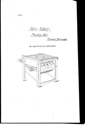
Page 1.
7768X
Hart & Holladay,
Thrashing Mach.
Patented Sep 17, 1833.
No specification available

Page 2.
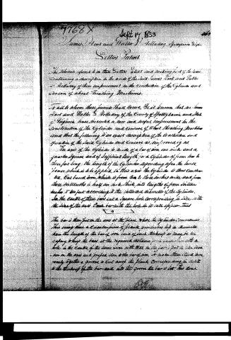
1768 X Sept 17 1839 463
James Hart and Walter S. Holladay, Spotsylvania Virginia
Setters Patent
The scheme referred to in these Letters Patent and making part of the same, containing a description in the words of the said James Hart and Walter S. Holladay of their improvement in the Construction of the Cylinder and Concave of Wheat Thrashing Machines.
To all to whom these presents shall come, Be it known that we, James Hart and Walter S. Holladay, of the County of Spotsylvania and State of Virginia, have invented a new and useful improvement in the Construction of the Cylinder and Concave of Wheat Thrashing Machines and that the following is an exact description of the Construction and operation of the said Cylinder and Concave as improved by us.
The axis of the Cylinder is made of a bar of iron one inch and a quarter square and of sufficient length for a Cylinder of from two to three feet long, the length of the Cylinder depending upon the horse power which is to be applied. In this axis the Cylinder is thus constructed, One broad iron, which is from two to three inches wide and from three sixteenths to half an inch thick, into lengths of from sixteen inches to two feet according to the intended diameter of the Cylinder. In the centre of these bars cut a square hole corresponding in size with the size of the axis. Each bar with the hole in it is called a "tied."
The bar is then put on the axis at the place where the Cylinder commences. This being done a circular piece of plank four inches less in diameter than the length of the bar of iron and of such thickness as may be necessary to keep the bar at the required distance from each other with a hole in the centre of the same size with that in the bar. Put the like pieces on the axis and project close to the bar of iron to make them stand more firmly together a groove is cut along the plank corresponding in depth to the thickness of the bar and into this groove the bar is let. This done
Page 3.
17687
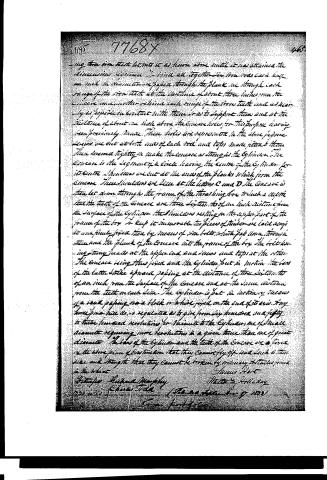
Another bar similarly made is put on in like manner, with this difference only that it is to stand at right angles with the first. Then add another piece of plank, and so on, in this manner the whole Cylinder is constructed. Each successive bar being iron at right angles with the preceding one, and as many bars and circular pieces of plank have been put on as may be necessary to make the Cylinder of the intended length. To hold the whole Cylinder firmly together four rows of iron each half of an inch in diameter are passed through the Cylinder, two on each side, one through one range of the bars, another through another range about three and a half inches from the ends of the bars or an inch and a half from the outer edge of the circular pieces of plank, holes having been previously made through them for that purpose. Screws are cut at the ends of the rods and taps are made adapted to them. These taps screwed tightly on hold the bars and pieces of plank firmly together that the Cylinder cannot be broken by any ordinary force applied to it. To prevent any motion of the Cylinder in the axis, iron collars are made on the axis against the terminating bars at each end of the Cylinder. The Cylinder is fixed in a box pressed as the base of threshing machines generally are.
The Concave is formed in the following manner. Plank five to six inches wide and of the same thickness with that used in constructing the Cylinder is sawed into lengths of about two feet and a half. A segment of a circle is then cut out of each piece as represented in the following figure, which gives a lateral view of it. The segment begins straight at A and ending at B.

The iron teeth shown in the representation above given by the figures 12, 3 can about six inches long and an inch and a half wide and about three eighths of an inch thick are then let into the plank to a depth corresponding with their thickness, between the points A and B, the ends of the teeth reaching about two inches below the surface of the Concave. Another plank of exactly the same size and form is then added and three similar teeth are let into it at precisely corresponding points. Thus the whole Concave is constructed by adding pieces of plank of like size and form to each bar.
Published accounts: journal notice
Notice in the monthly list of patents, with remarks
Journal of the Franklin Institute, new ser., vol. 13 (1834), p. 249 · View the page
31. For a Thrashing Machine; James Hart, and Waller S. Holladay, Spottsylvania, Virginia, September 17.
Remarks. This patent is taken for the manner of constructing the cylinder and concave, which is as follows. A square bar of iron is to form the shaft of the cylinder; the gudgeons, of course, being rounded. Flat bars of iron, from sixteen inches to two feet in length, are to have square holes made through their centres, so that they will slip on to the shaft. One of them is to be put on, and against it a circular piece of plank, four inches less in diameter than the length of the bar, leaving the latter to project two inches, to form teeth, or beaters; the plank, by its thickness, regulating the distance of the teeth. A second bar is to be placed against this plank, at right angles to the former, then another plank and another bar, until there are enough for the length of the cylinder. For the sake of greater firmness the bars are let into the plank; and to keep the whole together, four screw bolts are to pass from end to end of the cylinder, through the plank and bars The concave is to be placed above the cylinder, and to be formed of plank, with projecting teeth, on the same principle. There is no claim made, but as the whole description consists in the manner of constructing the cylinder and concave, the object of the patent is sufficiently apparent.
About this record
- Patentee
- DATAMP
- Date
- the Name and Date index of patents, DATAMP, USPTO records
- Invention
- DATAMP
- Listed in
- the Name and Date index of patents, DATAMP, USPTO records, Jim Shaw's X-patent list, the Journal of the Franklin Institute, Burke's List of Patents (1847)
- Burke's 1847 Patent Office list gives the same patent.