

Drawings and documents
USPTO scan
The patent as scanned by the USPTO
-
 Page 1
-
 Page 2
-
 Page 3
-
 Page 4
-
 Page 5
-
 Page 6
-
 Page 7
-
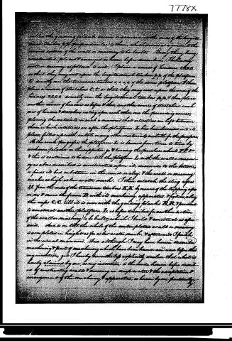 Page 8
-
 Page 9


U.S. Patent and Trademark Office · Google Patents
Show the transcription Hide (2,787 words)
Machine transcription (LightOnOCR) of the pages as scanned by the USPTO, most of them the handwritten copies made when the records were restored after the 1836 fire. Not checked; it can misread handwriting, so compare it with the scan.
Page 1.
7778X
H. R. May
Building Walls in deep Water
Patented Sept. 23, 1833
Fig. 1

Page 2.
7778X
H. R. May
Building Walls in deep Water
Patented Sept. 23rd 1853
Fig. 2

Page 3.
9/23/1833 7778x
Henry M. Bray.
Letters Patent.
The Schedule referred to in these Letters Patent and made up part of the same containing a description in the words of the said Henry M. Bray himself of his Improvement in Building Walls in Deep Water.
Know all men by these Presents
That I Henry M. Bray of the City of Boston in the County of Suffolk & Commonwealth of Massachusetts Gentlemen, have invented made & applied to use, a new & useful improvement in the mode of constructing walls & embankments in deep water not known or used before this my invention which said invention, & the principles thereon & the mode in which I have constructed its application with the manner of using the same are as follows to wit: 1st I drive in the usual way or by any convenient means a row or line of piles, each pile being driven at a suitable distance from the other, upon one side of the space on which the wall is to be erected or the embankment. 2nd I drive as far as possible another or second row of piles, each one of which being driven on the other side of the space or embankment but opposite to & in a direction parallel to the first row or line of piles. 3rd The two rows or lines of piles being placed as near as possible on the two sides of said space opposite & parallel to each other, I strengthen & sustain them in their proper positions by driving a placing upon them diagonally to every pile or every other one in the series, properly fixing & securing them on the alternate sides of the piles & placing the lower ends of the same at a suitable distance from the foot of each or every other pile. They being fastened by bolts or otherwise, at some distance from the top of the piles to the same on the alternate sides. 4th I form in the usual way each of said rows or lines of piles driven & secured as aforesaid. I apply upon the tops of each row by any convenient means a continuous coat of sufficient strength & dimensions extending from one end of each row of piles to the other end of the same row, thereby forming
Page 4.
7778X
two level caps, or parallel lines of pile. 5th. I construct a frame of suitable form, and materials containing winch laps with their shafts, by wheels, pinions and supports a platform for the workman who may be employed to work the apparatus and machinery.
6th. I place the frame with its machinery and apparatus upon the caps or ends of piles so that the said frame with its machinery and apparatus may be moved backwards and forwards, or along the parallel lines as occasion may require. The platforms or supports for the workmen, and the purchase or arms or wheels of the winch laps being above on the outer side or extending beyond the said rows or lines of piles, and the other parts of said machinery and apparatus being above between the two rows of piles of said caps.
7th. I construct a platform of transverse and longitudinal timbers of sufficient strength and dimensions placing the longitudinal timbers upon the transverse ones at right angles with them within about four inches of the ends of the same, and fasten them together with tenails or in any other suitable way; the length of the transverse timbers being about equal to the width of the space to be filled up between the rows of piles of said caps, and the longitudinal timbers extending as far as may be necessary for the construction of any section of the wall or masonry to be built, against the ends of said longitudinal timbers, I fasten planks perpendicular to them with spikes, which serve as guides in its passage downwards for the same section of the wall or masonry to be built.
8th. This platform I place between the two rows of piles and beneath the winch laps frame and in such a manner that the transverse timbers shall be across and over the space to be built upon, while the longitudinal timbers extend along the said space in lines parallel to the two rows of piles of said caps and here over the water of said frame, between said rows of piles. I sustain the aforesaid platform by means of ropes or slings; the loops of which being placed around the inner sides of the ends of said transverse timbers, while the other ends of said ropes or slings are fastened to the blocks belonging to the winch laps of said caps.
9th. The platform of transverse and longitudinal timbers being thus made, placed and firmly held over the space to be filled up or wherein the wall or masonry is to be constructed between the two parallel lines or rows of
Page 5.
7778X
195.
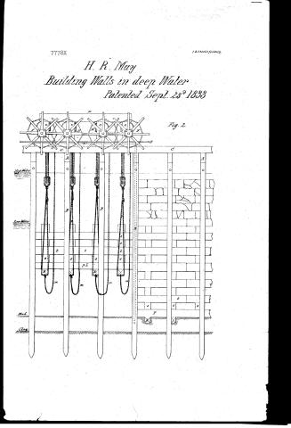
fils as aforesaid. I place upon said platform alternate courses of stone in the form of courses of headers and stretchers with interstices between them, the first course of headers being resting upon the longitudinal timbers directly over the transverse timbers of the platform, and the first course of stretchers resting upon the ends of the headers, directly over to the longitudinal timbers, the second (remaining) courses of headers and stretchers resting upon one another over the former courses so that interstices are left between the stones, which after the platform has been lowered into its place are filled with rubble or large stones, and as fast as the work progresses I lower the same into the water by the means of the wind-laps and apparatus aforesaid, and this I continue to do until the platform rests on the bottom and the wall rises as high as low water mark, and then the ropes or slings are drawn off of the ends of the transverse timbers by means of tripping ropes connected with said ropes or slings for the purpose, and the remaining or upper part of the wall is finished in the usual or any convenient way. 10th. One section of the said wall being thus completed, I move the wind-laps frame with its apparatus along the side rails until it comes to the end of the platform and section of wall already so built, and proceed to construct, place and sustain another platform of transverse and longitudinal timbers as aforesaid, and this also is furnished with alternate courses of headers and stretchers as aforesaid. I lower this second platform down in the manner above described until it sinks to the bottom of said space to be filled up, the planks at the end of the first platform serving as a guide for the second, and those of the second as a guide for the third and so on. And in this manner I construct platform after platform and section after section, until the entire wall or masonry upon the space between the two rows of piles aforesaid shall be done and completed. It is obvious that the wind-laps frame, platform of transverse and longitudinal timbers with the other machinery, apparatus and fixtures aforesaid must be varied in number and dimensions according to the nature and extent of the space, on which the wall or masonry is to be constructed. The description above given may perhaps be better understood by reference to the drawing hereto annexed and the explanation of the same which is as follows to wit: Figure 1 exhibits an end view of
Page 6.
the two rows of piles. the windlapes platform & machinery & apparatus Fig. 1. is being a view of the same. A.A. the rows of piles driven parallel to each other between which the wall is to be built with a space sufficient to allow the platforms to pass over between them unobstructed. B.B. the open shores on the external sides of the piles A.A. which serve to strengthen and support them. C.C. the caps to the two rows of piles A.A. on which the frame D. is made to move forward backward as occasion may require. D. is the frame of the principal machinery & is composed of two external longitudinal sills a.a. and four transverse sills y.y.y.y. suitably connected together by mortises & tenons & two external upper longitudinal beams l.l. resting upon the tops of the posts c.c.c.c. & secured to them by mortises & tenons & the posts c.c.c.c. rest upon the external longitudinal sills a.a. perpendicularly & are secured to them by mortises & tenons y.y. are transverse cross ties resting on the tops of the posts c.c.c.c. & mortised & tenoned at their ends into the longitudinal beams l.l. The frame D. may be varied in its dimensions & in the number of its sills, beams & posts according to the dimensions of the wall to be constructed & other circumstances. E.E. the common windlapes having journals at each of their extremities which revolve in boxes affixed to post c.c. The outward ends of said windlapes have attached upon their journals shafts or wheels of proper size which are set upon & turned round by the teeth of pinions fixed upon the ends of the shafts e.e. of the arms or puncher wheels P.P. which shafts revolving in proper bearings affixed to the posts c.c.c.c. have upon their opposite ends a set of puncher arms by which the workman operates the machinery. I see four puncher or armad wheels P.P. P.P. on each side of frame D. but every other one of the series is attached to a shaft the end of which extends beyond the external sides of the frame D. a sufficient distance, not to interfere in their movement with each other & to allow the workman to pass forward & backward on a separate platform g. placed in the space between the puncher wheels nearest to the frame D. and those farthest from it. The number of the wheels & shafts with the gearing and arrangement may however become varied & the same purpose answered. g. the platform & supports extending along the
Page 7.
7778X
137.
the interior sides of the frame D, in the space between the purchase wheels T, T, moves to the frame D, and the purchase wheels T, T, fasten from its properly fixed arrangement for the mechanism to stand upon which holds the machinery, a purchase wheel M, M. The common tackle purchase blocks, one block, in the set, is attached, or suspended from the upright column F, it moves still in its operation, in the usual way, to the other of the same set by a rope. One end of said rope is fixed to the arm of the block the rope is moved upon, a movement from the same, as the purchase wheel T, is moved forward or backward, but different blocks, or a greater or less number may be used & the gearing somewhat varied & the same effect obtained. To the lower block of the set M, is attached a rope I (called a sling rope) which passes around the interior end of the transverse sill or timber K, of the platform I, and serves to sustain the platform. At the lowermost point of the sling rope I is attached a rope M, called a tripping rope which serves when pulled to detach the sling rope I from the transverse timber K, after the platform I, has been let down to its base or bearing in the mud or clay in the bottom. When the sling rope I cannot be thus detached, as sometimes is the case, from the end of the transverse timber K, by the tripping rope M, in consequence of some obstacle in the bottom near the end of said timber, the sling rope may be removed by unfastening the lashing which is properly fixed for the purpose & then drawing the sling rope from beneath the timber in a direction at right angles to it. I use on each side of the frame D four small sets of purchase blocks, with suspension sling & tripping ropes, as above described, with the gearing & arrangement as aforesaid, but the number arranged in the gearing & arrangement may be varied & the same effect accomplished. To the platform in which the wall or masonry is to be laid, it is composed of long transverse timbers a, a, a, a, a, a, a, a, …
Page 8.
7778X
called the guiding plank, as soon as a course is made across of the longitudinal timbers f, f, f, perpendicular to them, which serves as a guide to the transverse section of the wall or masonry to be built. Every thing being constituted, placed & arranged as herein before described, I shall now proceed on masonry as follows to wit. I place a course of headers 3333 so that they may rest upon the longitudinal timbers f, f, f, of the platform I. directly on the transverse timbers c, c, c, of the same platform. I then place a course of stretchers t, t, so that they may rest upon the ends of the headers 3333. directly on the longitudinal timbers f, f, f, I then place another course of headers as before & then another course of stretchers, each row of headers & stretchers resting upon each other on the preceding course; placing the materials in such a manner that interstices are left between them which interstices are after the platform I. has been lowered into its place, filled up with rubble or any other materials suitable for the purpose. As the work proceeds the platform I. is lowered from time to time by workmen placed on the supports g, & turning the funnels wheels K, K, &c & this is continued to be done till the platform I. with the wall or masonry as above described is constituted upon it, descends to the bottom, & finds its bed or bottom in the mud or clay & the wall or masonry reaches as high as low water mark. I then detach the sling ropes H. from the ends of the transverse timbers K, K, by means of the tipping ropes m, m, & move the frame D with its machinery, apparatus, & spindles, along the rails C, C, till it is even with the guiding planks R, R, & proceed to construct another platform I. as before described for another section of the wall or masonry to be built, which I shall & construct as afore said. Thus is on till the whole of the contemplated wall or masonry is completed in height as far as low water mark. & afterwards I finish in the usual manner. And although I may have herein described machinery & parts of machinery which have been known and used before this my invention, yet I hereby nevertheless explicitly declare that what is hereby claimed by me, as my invention is the mode herein before described of constructing walls & masonry in deep water & the exceptional arrangement of the machinery & apparatus, as herein by me particularly
Page 9.
7778x
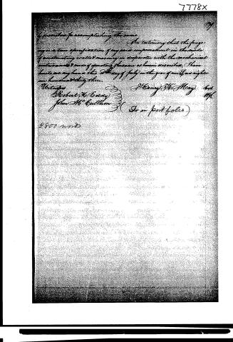
If described for accomplishing the same.
In testimony that the foregoing is a true specification of my said improvement in the mode of constructing walls & masonry in dry water with the mechanical utensils and mode of operating the same as herein described, I have hereunto set my hand this 20th day of July in the year of our Lord one thousand eight hundred and thirty-three.
Witnesses
Robert McCooley
John McCallum
Henry F. McRay, Esq.
Dr. in post folio
2800 words
Published accounts: journal notice
Notice in the monthly list of patents
Journal of the Franklin Institute, new ser., vol. 13 (1834), p. 257 · View the page
47, For an improved Mode of Building Walls in deep Water; Henry K. May, Boston, Massachusetts, September 23.
About this record
- Patentee
- DATAMP
- Date
- the Name and Date index of patents, DATAMP, USPTO records
- Invention
- DATAMP
- Listed in
- the Name and Date index of patents, DATAMP, USPTO records, Jim Shaw's X-patent list, the Journal of the Franklin Institute, Burke's List of Patents (1847)
- Burke's 1847 Patent Office list gives the same patent.