

Drawings and documents
USPTO scan
The patent as scanned by the USPTO
-
 Page 1
-
 Page 2
-
 Page 3
-
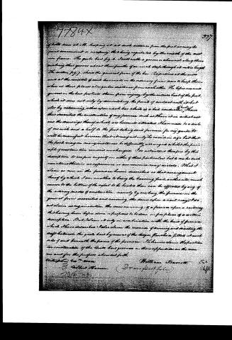 Page 4


U.S. Patent and Trademark Office · Google Patents
Show the transcription Hide (865 words)
Machine transcription (LightOnOCR) of the pages as scanned by the USPTO, most of them the handwritten copies made when the records were restored after the 1836 fire. Not checked; it can misread handwriting, so compare it with the scan.
Page 1.
7784X. W. Barrett.
Evaporating Pan.
Patented Nov. 19, 1833.
Fig. 1
Fig. 2
Fig. 3
Fig. 4
Fig. 5
Fig. 6
Fig. 7
Page 2.
Nov 19, 1833
William Barnett
Letters Patent
The Schedule referred to in these Letters Patent and making part of the same containing a description in the words of the said William Barnett himself, of his Improvements on Furnaces for burning Anthracite coal for heating & evaporating Liquids.
To all whom it may concern. Be it known that William Barnett of Salem in the County of Middlesex and State of Massachusetts have invented certain improvements in furnaces for the purpose of burning the different varieties of Anthracite coal and applying the heat from the same to the heating of vessels used for the purposes of Drying, Distilling, Brewing, Soap-making, evaporating steam and in general wherever it is required to heat or evaporate fluids of any kind by a heat convection or improvements thereon to a considerable extent the expense of fuel and the time required for attendance on the fire effect a more rapid heating of the fluids by a more immediate application of the fire to the bottom of the containing vessel and withdraw or apply the fire with greater facility than by any of the methods heretofore known. Preserve the grate bars from the effects of the intense heat of the furnace and obtain other advantages. The grate with its appendages which is used for sustaining the fuel is made to run upon a rail way by means of iron trucks or rollers, from which circumstance I designate this furnace the "railway furnace" and I do hereby declare that the following is a full and exact description of the construction thereof, reference being had to the drawings which accompany and make a part of this specification. Fig 1 is a sectional view of the furnace cut vertically from front to back. Fig 2 is a vertical transverse section thereof. Fig. 3 is a horizontal section or plan with a boiler and superheater tube which surrounds it removed leaving the furnace and its immediate appendages in view. Fig 4 shows the under side of the Grate, its frame and trucks, &c. Stokers upon which it runs. Fig 5 is a side view of the same. Fig 6, the upper surface of one of the bars. Fig 7 is a transverse section of the same. In referring to the respective figures I shall merely
Page 4.
of better seen at all, keeping it at such distance from the fuel as may be found convenient or necessary, that being regulated by the width of the cast iron frame. The grate has fig. 6. Seats with a groove or channel along them making that groove about three fourths of an inch deep through its entire length. The section fig. 7. shows the general form of the bar. Projections at the inner end at the middle of each bar made in the ordinary form serve to keep them when in their places at regular distances from each other. The before named grooves on the bars protects them from injury by the intense heat of the fuel, which it does not only by diminishing the points of contact with it but also by retaining ashes upon each bar which is a heat conductor. I have thus described the construction of my furnace such as I have it in actual use and the drawings thereof which are herewith attached I have made to a scale of one inch and a half to the foot taking said furnace for my guide. It will be manifest however that it may not only be varied in size but that the parts may in many instances be differently arranged whilst the principle of construction remains unchanged. I do not enter therefore by this description to confine myself on either of these particulars but to make such variations therein as experience or convenience may dictate. What I claim as new in the furnace herein described is that arrangement thereof by which I am enabled to bring the burning fuel, and the air, much nearer to the bottom of the object to be heated than can be effected by any of the ordinary modes of construction, namely by making the furnace in the general form described and running the combustion air in a way. I do not claim as my invention the mere running of a furnace upon a railway this having been before done or proposed to be done, in fine places of a certain description. But I claim it only in combination with the kind of furnace which I have described. I also claim the manner of drawing and meeting the draft between the grate bars by means of the larger flanches or fillets at each side of and beneath the frame of the furnace. I likewise claim the particular construction of the grate bars grooves on their opposite sides on the manner and for the purpose above set forth.
Witnessed to: Wm.
William Barnett Esq.
Chf.
To: Gilbert Hannon.
13/6/34
Published accounts: journal notice
Notice in the monthly list of patents, with remarks
Journal of the Franklin Institute, new ser., vol. 13 (1834), p. 260 · View the page
6. For an improved Furnace for Burning Anthracite Coal, for Heating and Evaporating Liquids, denominated the "Railway Furnace;" William Barrett, Malden, Middlesex county, Massachusetts, November 19.
Remarks. The ends which are said to be attained by the use of the furnace here patented, are, "the lessening, to a considerable extent, the expense of fuel, and the time required to attend on the fire; a more rapid heating of the fluid by a more immediate approximation of the fire to the bottom of the containing vessel; the withdrawing and applying the fire with greater facility than by any of the methods heretofore known, and the preserving of the grate bars from the effect of the intense heat of the furnace." "The grate, with its appendages, which is used for sustaining the fuel, is made to run upon a rail-way, by means of iron trucks, or rollers, from which circumstance it is denominated The Rail-way Furnace." The part of the specification which follows the foregoing quotation, refers to a well executed drawing of the apparatus, the general nature of which may, however, be understood without it. The carriage, or frame, which sustains the grate bars, brings the fuel as near to the bottom of the boiler as possible, and is so enclosed that no air can enter excepting that which passes through the fuel. The grate bars are cast with a groove, or channel, along their upper sides, which groove may be three-fourths of an inch deep; this "groove in the bars protects them from injury by the intense heat of the fuel; which it does, not only by diminishing the points of contact with it, but also by retaining ashes upon each bar, which is a bad conductor of heat." The claim is in the following words1 "What I claim as new in the furnace herein described, is that arrangement thereof by which I am enabled to bring the burning fuel, anthracite, much nearer to the bottom of the vessel to be heated than can be effected by any of the ordinary modes of construction, namely, by making the furnace in the general form described, and running the same upon a rail-way. I do not claim as my invention the mere running of the furnace upon a rail-way, this having been before done, or proposed to be done, in fireplaces of a certain description, but I claim it only in combination with the kind of furnace which I have described. I also claim the manner of securing and directing the draft between the grate bars by means of the ledges, flanches, or fillets, on each side of, and beneath, the frame of the furnace. I likewise claim the particular construction of the grate bars, grooved on their upper sides, in the manner, and for the purpose, above set forth."
About this record
- Patentee
- DATAMP
- Date
- the Name and Date index of patents, DATAMP, USPTO records
- Invention
- DATAMP
- Listed in
- the Name and Date index of patents, DATAMP, USPTO records, Jim Shaw's X-patent list, the Journal of the Franklin Institute, Burke's List of Patents (1847)
- Burke's 1847 Patent Office list gives the same patent.