

Drawings and documents
National Archives restored drawings: drawing
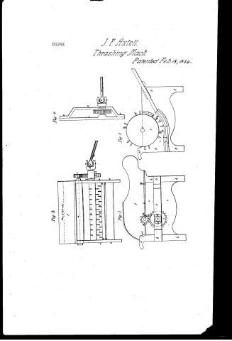
J.F. Axtel's Patent Drawing for a Thrashing Machine

National Archives, Restored Patent Drawings (Record Group 241) · Full-size scan at the National Archives · Catalog record
Show the text on the drawing Hide (49 words)
Words on the drawing as machine-read by the National Archives; not checked. Useful mainly for searching.
130. THRASHING. / Entered / Thrashing Machines. / A. Cylinder Machines. / J. F. - AXTELL. / 8024 / DIVISION. / Patented 18 the Feb 1834. / THRASHING MACHINE. / Plate No 2. / of / cylinder / f. / Plate No 4. / Pla te No1. / ai / Is / 02 / Plate V3. / Ld / ~ ~ / Cla. / Пр
USPTO scan
The patent as scanned by the USPTO
-
 Page 1
-
 Page 2
-
 Page 3
-
 Page 4


U.S. Patent and Trademark Office · Google Patents
Show the transcription Hide (1,055 words)
Machine transcription (LightOnOCR) of the pages as scanned by the USPTO, most of them the handwritten copies made when the records were restored after the 1836 fire. Not checked; it can misread handwriting, so compare it with the scan.
Page 1.
8024X
J. F. Axtell.
Thrashing Mach.
Patented Feb. 18, 1834.
Fig. 1
Fig. 2
Fig. 3
Fig. 4
Page 2.
Feb. 18, 1834
Vehiel F. Axtell Genesee N.Y.
Letters Patent — February 18, 1834.
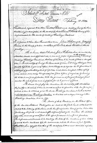
The schedule referred to in these Letters Patent and making part of the same containing a description in the words of the said Vehiel F. Axtell himself of his improvement in the mode of making threshing Machines.
To all persons to whom these Presents shall come, Vehiel F. Axtell of the Village of Genesee in the County of Ontario and State of New York, Greeteth:
Be it known that I the said Vehiel F. Axtell have in consideration the money subscribed made and applied to use, a new and useful improvement in the manner of making threshing Machines, the sides of the same to be made of cast or wrought iron. The advantage of having the same made of iron, is its being stronger, more durable, less liable to get out of repair, more steady and regular in its operations, and although of greater strength, it is of less size and, more compact, takes up less room and is more easily transported from place to place if required; by having the sides in one piece of metal with the grooves and flanges forming a part makes the whole firm and impossible for it to get out of place.
The small compass of the machine, the durability of its materials, the facility with which it can be moved and put in operation, and the low price for which it can be obtained gives the said threshing machine which is called a 4 or 6 bolt cast iron threshing machine, a decided advantage over any other threshing machine now in use.
The mode of said Machine is the Patent Office of the United States at Washington as well as the plates hereto attached &c. 1, 2, 3, 4, & the lettering of the same with the specification thereof given herein the particular details and describe the different parts of the machine, the distinct operation and use of each part & the effect produced when put in operation.
The improvement claimed is in making the sides of the machine of iron instead of wood & other materials & for the manner in which the same is put together.
See Fig. 1 an upright side view of the machine, lettered and described as follows.
Page 3.
Letters a a upright side plates of the machine made of cast iron the ends of the plate being raised & forming the legs of the machine as represented by letters f, f, the top of the plate forming a flange as represented by letter h, which supports the cap of the machine letter f, h a brace or rest attached to the main plate by bolts or screws supporting the out-end of the journal of the main wheel and to those which the main plate the main wheel moves the journals of the main wheel being confined on the rest by a coupling as represented by S, in plate C to y the brace or rest is more plainly represented in plate C to 4 by letter h. C the main wheel of machine washing into pinion wheel b, c c a universal joint attached to journal of main wheel connecting the machine with the power by which it is propelled & the side of the cap of machine made of iron which can be taken off at pleasure. g g pins attached to the cap passing thru the flange h, and confining cap to main plate h the top part of main side plate forming a flange projecting to the front thru its lock pins g, g, f, f.
i i i i bolts or screws confining the machine together S S Coupling confining the journals of pinion wheel to said plate Plate C to 2 an end view of the machine Letters a a edges of the side plates forming the legs which support the machine - b the brace or rest - C C the main wheel - d d the universal joint connecting the machine with the power applied to letter N, e e the shaft e e e e the teeth or spikes in the cylinder and concave of machine as will more clearly appear in plate C to 3. f the cap of the machine covered with sheet iron i i the bolts or screws connecting side plates with timbers j k, m, l lower part of frame between side plates k the apron board joined to the concave let into side plates by means of grooves in the side plate as represented by letters o o in plate C to 4 8 8. g pinion wheel washing into main wheel and driving the cylinder k m plate C to 3. n the top of frame between side plates n the shaft Plate C to 3. an upright inside view of side plates Letters o o the side plate - t an end view of cylinder a a d. C t grooves in which the apron concave and spikes are placed e e e e e the teeth or spikes fixed in concave and on cylinder which thrash the grain f the journals of the cylinder l c bolts or screws l c c c c c flanges cast on plate forming grooves as represented in plate C to 2 by letters r r o o Plate C to 4 a horizontal view of the side plate.
Page 4.
8024X 91
rest, main wheel, universal joint line shaft, &c. Set on a top of plate to the brace or rest supporting journal of main wheel, so the main wheel is a universal joint &c. to bolts or screws, connecting brace or rest with side plate of machine - a line shaft & coupling, connecting journal of main wheel to the brace or rest. In testimony that the above is a true specification of my said improvement as above described called "Ottawa Cast Iron Striking Machine," I have hereunto set my hand this 23rd day of June 1833.
Witnesses
Sam'l Mort
C Rodney
Silas A. Astor
Drawing
1104 words
End.
MGC
Published accounts: journal notice
Notice in the monthly list of patents, with remarks
Journal of the Franklin Institute, new ser., vol. 14 (1834), p. 188 · View the page
36. For a Thrashing Machine; Jehial F. Axtell, Geneva, Ontario county, New York, February 18.
Remarks. It is unnecessary to describe this machine, as the thing claimed does not confine the invention, or discovery, to machines of any particular construction, but extends to all, past, present, and to come. "The improvement claimed is in making the sides of the machine of iron, instead of wood and other materials, and for the manner in which the same is put together," the said improvement being called "Axtell's Cast Iron Thrashing Machine." If we read the patent law, and the decisions under it aright, such a patent is of no value; there is neither invention or discovery in the thing; every body knows that the sides of such a machine might be made of cast iron, and that it might be put together by means of flanches and screw bolts. If this patent is good, so would another be for a machine in all respects similar, but cast of zinc, or any other metal, or metallic compound, than iron. It is a mere change of material.
About this record
- Patentee
- DATAMP
- Date
- DATAMP, USPTO records
- Invention
- DATAMP
- Listed in
- the Name and Date index of patents, DATAMP, USPTO records, Jim Shaw's X-patent list, the Journal of the Franklin Institute, Burke's List of Patents (1847)
- The sources give different dates; the date shown is the one most of them agree on.
- The Franklin Institute's journal confirms the date shown.
- Burke's 1847 Patent Office list gives the same patent.