

Drawings and documents
National Archives restored drawings: drawing
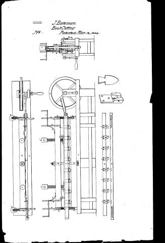
Jonas Bateman's Patent Drawing for a Machine for Cutting and Trimming Books


National Archives, Restored Patent Drawings (Record Group 241) · Full-size scan at the National Archives · Catalog record
Show the text on the drawing Hide (153 words)
Words on the drawing as machine-read by the National Archives; not checked. Useful mainly for searching.
Sheet 1. 11. BOOK-BINDING. / CLASSIFICA / [15] Book Cutting. / 8068-X / Jonas Batman / DIVISION / butting 02 Trimming Bookso 02 Paper. / Vol. 18. pg. / Patented harch / e' / Patentid march 12th 1834 / ou / Preferences. / platform lower bar / e centre bar or follo / d, C.C upper far / iron plates / centre iron bolt. / If iron bands. folts / iron / i.i crop with / K.K. / sha / l.l. small pins. / m. m / n.n. cords / 0.0 pullegs / pp / q the knife far / y.r. slits / Jocke / U.U. laye iron / v.fly wheel. / w pitmand / N crank. / Knife far towards the press / :: / 00 / 00 / Patent affice august 31" 1841 / made under the direction of the Commissioneral / in conformity with act of march 1837. / the hnife bar. bar. / viewofarknife.S. view of a / Perspective viewofa viewofn Jocket. / Commissioner of Patents.
Sheet 2. Return to DRAFTSMAN. / BOOK BINDING. / Book Cutting / J.Bateman. / BookCutting. / No / PatentedMar.12, 1834. / Ou / ye / 8068XA
USPTO scan
The patent as scanned by the USPTO
-
 Page 1
-
 Page 2
-
 Page 3
-
 Page 4
-
 Page 5


U.S. Patent and Trademark Office · Google Patents
Show the transcription Hide (1,536 words)
Machine transcription (LightOnOCR) of the pages as scanned by the USPTO, most of them the handwritten copies made when the records were restored after the 1836 fire. Not checked; it can misread handwriting, so compare it with the scan.
Page 1.
8068X
J. Bateman.
Book Cutting.
Patented Mar. 12, 1854.
Page 2.
3/12/1834 8068X
Mar. 12, 1834 319.
Jonas Bateman
Letters Patent
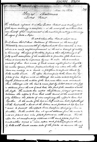
The Schedule referred to in these Letters Patent and making part of the same containing a description in the words of the said Jonas Bateman himself of his improvement in the machine for cutting or trimming the edges of Books or Paper.
To all to whom these Presents shall come
Be it known that I Jonas Bateman of Harvard in the county of Worcester & Commonwealth of Massachusetts have invented a machine or a new & useful improvement in the art or business of cutting or trimming the edges of Books or paper & that the following is a fully exact description of the construction & operation of the said machine as invented & improved by me to wit: Said machine consists of three bars made of hard wood eight feet in length & six inches square placed perpendicularly one above the other the lower one resting on a bench or platform & confined thereto by bolts, nuts & screws. The upper bar is confined to the lower bar by plates of iron half an inch in thickness two inches wide & two feet in length placed on the outside of the bars near their ends and sink their thickness into the bars & made fast by bolts & screws at a proper distance from the ends of said bars. This part of the machine is called the prefs. The middle bar called the follower plays up & down between the upper & lower bars with tenons at the ends so as to play between the plates of iron confining the upper & lower bars together. In the centre of the bars an half inch iron bolt passes through all the bars with a head at the bottom and fastened at top by a nut or screw to prevent the upper & lower bars from springing when in operation. On the middle bar at equal distances from the centre & ends are placed two iron plates fastened on with screws. To the upper bar at corresponding distances with said plates fastened with screws either iron or iron upon said plates confined thereto by bolts with heads under side of the plates so as to secure the middle
Page 3.
3/12/1834 8068X
321
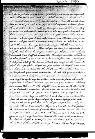
the bar or follower up or down by turning the screws one way or the other. These screws serve to confine the books or paper between the lower & middle bars so as to be operated upon. Thus the upper lower bars one inch from the ends pass in an horizontal direction four three fourths inch iron bolts with an eye in each three fourths of an inch in diameter & screws cut in the eyes of the lower ones. Said bolts are confined on the opposite side of the bars with pins & screws. In the eyes of these bolts moves two turned iron perpendicular shafts with a screw cut six inches on the lower ones up to the lower bearings & corresponding with the screws cut in the eyes of the bolts. These shafts are two feet six inches in length. The lower bearings are three fourths of an inch in length & one inch & an half in diameter, the shafts are then turned down to three fourths of an inch in diameter & four inches in length to play in slots of the bar in which are confined the knives. The upper bearings of the shafts are five inches in length & one and an half inch in diameter the shafts are then to their tops turned to three fourths of an inch diameter. On the top of each shaft is a crag made of half an inch square iron with arms nine inch in long & a right angled elbow nine inches from the centre six inches in length turned up on one of said arms. Said crags are riveted on to the shafts & move round with the shafts in an horizontal direction. On the upper bar on the side where said shafts are two other perpendicular shafts made of half inch iron fourteen inches long are attached to said bar nine inches distant from the centre of the large shafts by a screw passing thru said shafts & the centre of the bar. These shafts are flat where they come against the bar & round where they rise above the bar & so fastened by the screws as to admit of small longitudinal motion. The lower ends of these shafts are parallel with the under side of the bar & then form a right angle, their towards the centre of the machine of an inch in length a small pin near the bottom of the bar prevents the bottoms of these shafts moving towards the centre of the machine.
Page 4.
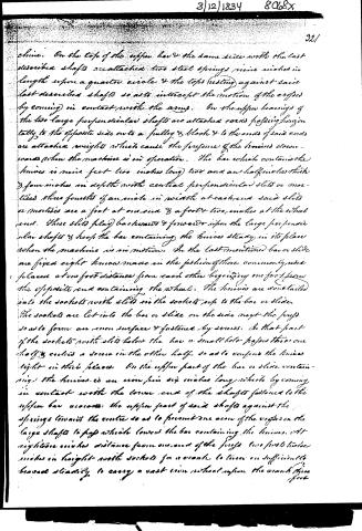
chine. On the top of the upper bar & the same side with the last described shafts are attached two steel springs nine inches in length upon a quarter circle & the tops resting against said last described shafts so as to intercept the motion of the cranks by coming in contact with the arms. On the upper bearings of the two large perpendicular shafts are attached cords passing horizontally to the opposite side onto a pulley & block & to the ends of said cords are attached weights which cause the pressure of the knives downwards when the machine is in operation. The bar which contains the knives is nine feet two inches long two and a half inches thick & four inches in depth with central perpendicular slits or mortices three fourths of an inch in width at each end said slits or mortices are a foot at one end & a foot two inches at the other end. These slits play backwards & forwards upon the large perpendicular shafts & keep the bar containing the knives steady in its place when the machine is in motion. On the last mentioned bar or slide are fixed eight knives made in the fashion of those commonly used placed at one foot distance from each other beginning one foot from the opposite end containing the wheel. The knives are dovetailed into the sockets with slits in the sockets up to the bar or slide. The sockets are let into the bar or slide on the side next the props so as to form an even surface & fastened by screws. In that part of the sockets with slits below the bar a small hole passes through one half & enters a screw in the other half so as to confine the knives tight in their places. On the upper part of the bar or slide containing the knives is an iron pin six inches long which by coming in contact with the lower end of the shafts fastened to the upper bar crosses the upper part of said shafts against the springs towards the centre so as to permit one arm of the cranks on the large shafts to pass while lower the bar containing the knives. At eighteen inches distance from one arm of the props two feet twelve inches in height with sockets for a wrench to turn on sufficiently broad steadily to carry a cast iron wheel upon the crank three feet
Page 5.
3/12/1834 8068x
322
foot in diameter & weighing one hundred pounds & runs partly in a mortise cut in the bench or platform are erected on the side in which the crank is turned. It is so bent as to form a sweep of six inches to which a reach or fetch fastened to a bolt in the bar or slide containing the knives also fastened by a socket. The crank is further so bent as to form another sweep of a foot at the handle taken hold of to turn it. By means of the connexion of the reach or fetch with the shaft of the crank & the bar or slide containing the knives to move in an horizontal direction alternately one foot each way at every revolution of the wheel & at each alternate movement the bar by means of the shafts & springs cross weights & screws is lowered & pressed down upon the book or paper to be cut or trimmed by the knives. These machines may be made on a larger or smaller scale than the one above described & with a greater or lesser number of knives & they may be operated with by manual, water or other power. The principles of this machine of which the said Jonas Bateman claims to be the inventor or discoverer are the simultaneous use of so many knives brought to bear upon the books or paper to be cut or trimmed by turning the balance wheel & the consequent operation of the weights, shafts, screws & springs above described.
Witnesses
Moses Smith
John Huntington
Jonas Bateman
Ford.
MGC.
[1521 and]
Published accounts: journal notice
Notice in the monthly list of patents, with remarks
Journal of the Franklin Institute, new ser., vol. 14 (1834), p. 241 · View the page
32. For a Machine for Cutting and Trimming the Edges of Books and Paper; Joseph Bateman, Harvard, Worcester county, Massachusetts, March 11.
Remarks. The machine here patented is clearly described in the specification, well represented in the drawing, and has the merit of differing essentially from those previously patented for the same object. The body of the machine consists of three parallel bars, which may be eight feet long, and six inches square, placed horizontally, one above the other, and supported at suitable distances apart by end cheeks, bolts, &c. The lower bar forms the bed upon which the paper to be cut is placed; the middle bar is the follower, which is forced down by screws, and presses the paper, or books, to be cut, and the upper bar serves for the pressing screws to work in. A sliding bar in front of the press, has in it eight knives, placed a foot apart; they are in form like the ordinary book binder's cutting knife, and are fixed in the sliding bar in such a way as to admit of their being properly adjusted, and the bar itself is so confined that whilst it slides freely, it can not swerve from its proper direction. A fly wheel and crank, connected to the sliding bar by a reach or pitman, gives to it the proper vibrating motion. The different adjustments we do not attempt to give, as these would require the whole specification. The claim is to "the simultaneous use of so many knives, brought to bear upon the books or paper to be cut, or trimmed, by turning the balance wheel, and the consequent operation of the weights, shafts, screws, and springs, above described."
About this record
- Patentee
- DATAMP
- Date
- the Name and Date index of patents, DATAMP, USPTO records
- Invention
- DATAMP
- Listed in
- the Name and Date index of patents, DATAMP, USPTO records, Jim Shaw's X-patent list, the Journal of the Franklin Institute, Burke's List of Patents (1847)
- The Franklin Institute's journal gives a different date.
- Burke's 1847 Patent Office list gives the same patent.