

Drawings and documents
USPTO scan
The patent as scanned by the USPTO
-
 Page 1
-
 Page 2
-
 Page 3
-
 Page 4


U.S. Patent and Trademark Office · Google Patents
Show the transcription Hide (1,433 words)
Machine transcription (LightOnOCR) of the pages as scanned by the USPTO, most of them the handwritten copies made when the records were restored after the 1836 fire. Not checked; it can misread handwriting, so compare it with the scan.
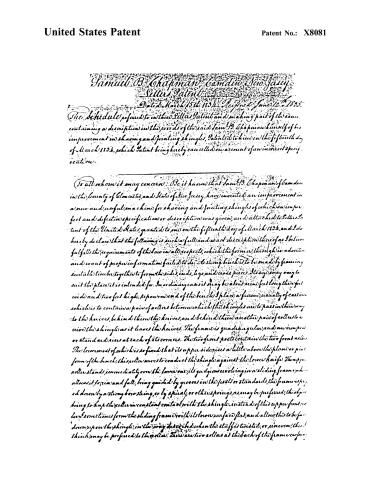
Page 2.
United States Patent
Patent No.: X8081
Samuel B. Chapman, Camden, New Jersey
Letters Patent
Dated March 15th 1834. Reissued June 12th 1835.
The Schedule referred to in this Letters Patent and making part of the same, containing a description in the words of the said Samuel B. Chapman himself of his improvement in shoving and jointing shingles, patented to him on the fifteenth day of March 1834, which Patent being hereby cancelled on account of an incorrect specification.
To all whom it may concern: Be it known that Samuel B. Chapman of Camden in the County of Gloucester, and State of New Jersey, have invented an improvement in a new and useful machine for shoving and jointing shingles of which an imperfect and defective specification or description was given, and attached to Letters Patent of the United States, granted to me on the fifteenth day of March 1834, and I do hereby declare that the following is such a full and exact description thereof as I believe fulfills the requirements of the law in all respects, which the former, through inadvertence and want of proper information failed to do: A strong bench is to be made by framing suitable timbers together to form the sides, ends, legs, and cross pieces. It may vary to suit the place it is intended for. In ordinary cases it may be about nine feet long, three feet wide, and two feet high. Upon one end of the bench I place a frame, usually of cast iron, which is to contain a pair of rollers between which the shingles are to pass in their way to the knives, behind them the knives, and behind them another pair of rollers to receive the shingles as it leaves the knives. The frame is quadrangular, and an iron post or standard rises at each of its corners. The two front posts contain the two front rollers. The lowermost of which is so fixed that its upper side rises a little above the plane or plane form of the bench; this roller serves to conduct the shingle against the lower knife. The upper roller stands immediately over the lower one, its guide being a sliding frame which allows it to rise and fall, being guided by grooves in the posts or standards, the frame is suspended down by a strong bow string, or by spiral, or other springs, as may be preferred, this object being to keep the roller in constant contact with the shingle instead of this upper front roller sometimes from the sliding frame with its lower surface flat, and allow this to be forced down upon the shingle in the way described when the stuff is twisted, or pine even, this thing may be preferred to the other. There are two rollers at the back of the frame, one for
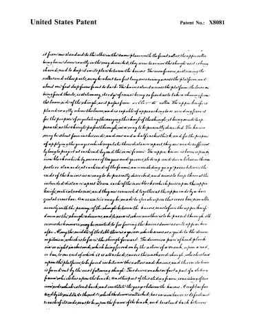
Page 3.
United States Patent
Patent No.: X8081
it from one standard to the other in the same plane with the front rollers, the upper roller being borne down exactly in the way described, they serve to receive the shingle as it is being shaved, and to keep it in its place between the knives. The iron frame, containing the rollers and other parts, may be about two feet long, measuring across the platform, and about one foot deep from front to back. The knives stand across the platform, the lower one being fixed thereto, is stationary, its edge of course being so fixed as to take a shaving from the lower side of the shingle, as it passes from roller to roller. The upper knife is placed exactly above the lower, and is capable of approaching to or receding from it for the purpose of regulating the varying thickness of the shingle, it being made to approach, as the shingle passes through, in a way to be presently described. The knives may be about four inches wide, and one and a half inches thick, and for the purpose of applying the gauges which regulate their distance apart, they are made sufficiently long to project at each end beyond the iron frame. The upper knife is borne upon iron blocks which by means of tongues and grooves, slide up and down between the iron posts or standards, at each end of the frame, an iron sliding gauge passes between the ends of the knives in a way to be presently described, and serves to keep them at the intended distance apart. From each of the iron blocks which press up on the upper knife, vertical rods rise, and they are connected together at their upper ends by a horizontal cross bar. An eccentric may be made to operate upon this cross bar, simultaneously with the passage of the shingle between the knives, so as to force the upper knife down as the shingle advances, and to raise it when another is to be passed through the cross rods; however, may be omitted, to for forcing the knives down as well as push them after. Along the middle of the table there is a groove, which serves as a guide to the driver or pitman, which is to force the shingle forward. The driver is a piece of hard plank six or eight inches wide, which being forced on by the action of a crank, upon a rod, or bar, to one end of which it is attached, causes the unshaved shingle, which is laid upon the platform, to be forced in between the rollers and knives, and this in its turn is forced out by the next following shingle. This driver makes in fact a part of a sliding frame which lies upon the bench. Another part of this sliding frame, consisting of two iron rods which extend back, and constitute the gauges between the knives. A cross bar fastened by its middle to the rod to which the driver is attached, has an iron bar or rods fastened to each of its ends, so as to be upon the frame of the bench, and to extend back between
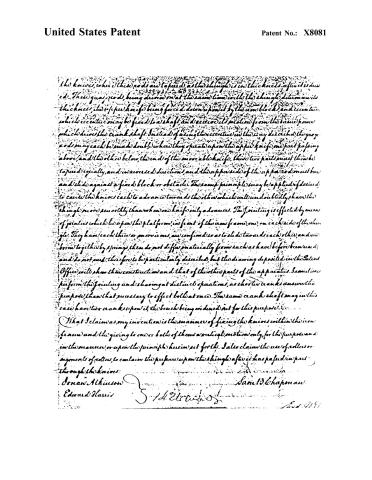
Page 4.
United States Patent
Patent No.: X8081
the knives, when these rods are tapered as the shingle is in the knives after it is driven. Their quays rods, being driven on at the same time with the shingle, determine its thickness, the upper knife being forced down upon it by the cam block, and eccentric, which eccentric may be fixed to a shaft and receive its motion from the same power which drives the crank shaft. Instead of fixing the eccentric in the way described, the quays rods may each be made double, where they operate upon the upper knife, one part passing above, and the other below, the end of the movable knife. These two parts must then be tapered equally, and in reversed directions, and the upper side of the upper rod must bow and slide against a fixed block or obstacle. The same principle may be applied if desired, to cause the knives each to advance towards the other, which will undoubtedly shave the shingle more smoothly than when one knife only advances. The jointing is effected by means of joints which lie upon the platform, in front of the cam frame, one on each side of the shingle. They have each their own motion, are confined so as to slide towards each other, and are borne together by springs, they do not differ materially from such as have before been used, and do not need, therefore to be particularly described, but the drawing deposited in the Patent Office will show their construction and that of the other parts of the apparatus. Sometimes perform the jointing and shaving at distinct operations, as short cranks answer the purpose, than that necessary to effect both at once. The same crank shaft may in this case have two cranks upon it, the bench being indicated not for this purpose.
What I claim as my invention is the manner of fixing the knives within the cam frame and the giving to one or both of them a vertical motion only, for the purpose and in the manner, or upon the principle herein set forth. I also claim the use of rollers or segments of rollers, to contain the pressure upon the shingle after it has passed in part through the knives.
Donau Alkinson
Edward Harris
Samuel Chapman
Published accounts: journal notice
Notice in the monthly list of patents, with remarks
Journal of the Franklin Institute, new ser., vol. 14 (1834), p. 245 · View the page
An upright post is to be fixed in the floor, its lower end being rounded, and passing into a socket to allow it to turn round. A sliding box, having a bottom or shelf, upon which to place the bag, and a back and sides to sustain it, slides up and down upon this post, by means of a socket or box, behind that which holds the bag. Upon the post there is a rack, into which a pall, or catch, falls, so as to hold the box at any height to which it is raised. A tackle, or other apparatus, may be used to raise the box and bag to a suitable height for shouldering, when, on removing the catch, the box will again slide down to the bottom of the post. 48. For a Machine for Shaving and Jointing Shingles; Samuel B. Chapman, city of Burlington, Burlington county, New Jersey, March 15.
Remarks. The description of this machine, and the drawing which accompanies it, have not sufficed to furnish us with a clear idea of its particular construction. The shingles, it appears, are to be forced between two knives parallel to each other, in doing which they are passed between two pairs of rollers, of wood or iron, one pair of which appears to be intended to guide them to, and the other to receive them in the delivery from, the knives. The jointing is to be effected by means of planes, each carrying three irons; but how the shingle is to be held whilst acted upon, does not appear. There is not any thing pointed out as new, or a claim made to any part of the apparatus.
About this record
- Patentee
- DATAMP
- Date
- the Name and Date index of patents, DATAMP, USPTO records
- Invention
- DATAMP
- Listed in
- the Name and Date index of patents, DATAMP, USPTO records, Jim Shaw's X-patent list, the Journal of the Franklin Institute, Burke's List of Patents (1847)
- Burke's 1847 Patent Office list gives the same patent.