

Drawings and documents
National Archives restored drawings: drawing
John Kinman's Patent Drawing for a Assistant Loader

National Archives, Restored Patent Drawings (Record Group 241) · Full-size scan at the National Archives · Catalog record
Show the text on the drawing Hide (125 words)
Words on the drawing as machine-read by the National Archives; not checked. Useful mainly for searching.
187 / ELEXWTORS / John Kinman / /4 / assistant loader. / Vol. i8 pg.43. / ESIFICATION / Patented Mar. 15.1834. / 80 8082-X - X / DIVISION. I / Jig.6. / OK / OIR / Ligh. / LU / WR / WR / EL / References. Q. the upright post. b pivot block. c floor. of notched far. e the guttered, / of wood. f ron hook g a small iron pin. h spring i the main box. K.K holes. / l. notch.mhook for the haisting 2ope .n box fastened to the main box. / Jig. lection Fig. 2 Iron view. Fig.3. backview. Tigh Topvicw. Jig 5 when at the floor. / Patent / Jig 6 illustrates the use of the assistant Coader. / made under the direction / Patents in conformity / ch.L. Theischmann feeit. / Herguy / Commissio
USPTO scan
The patent as scanned by the USPTO
-
 Page 1
-
 Page 2
-
 Page 3
-
 Page 4
-
 Page 5
-
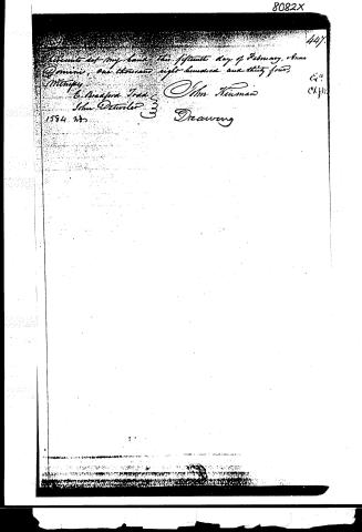 Page 6


U.S. Patent and Trademark Office · Google Patents
Show the transcription Hide (1,547 words)
Machine transcription (LightOnOCR) of the pages as scanned by the USPTO, most of them the handwritten copies made when the records were restored after the 1836 fire. Not checked; it can misread handwriting, so compare it with the scan.
Page 1.
8082X
J. Kinman
Elevator.
Patented Mar. 15, 1834.

AM. PHOTO-LITHO. CO. N.Y. (OSBORNE'S PROCESS)
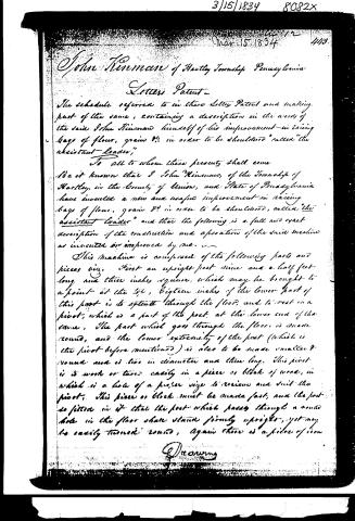
Page 2.
3/15/1834 8082X
Mar. 15, 1834 4/13
John Kinnman of Hartley Township Pennsylvania
Letters Patent
The schedule referred to in these Letters Patent and making part of the same, containing a description in the words of the said John Kinnman himself of his improvement in raising bags of flour, grain &c in order to be "shouldered" called "the assistant-loader,"
To all to whom these presents shall come
Be it known that I John Kinnman, of the Township of Hartley, in the County of Union, and State of Pennsylvania have invented a new and useful improvement in raising bags of flour, grain &c in order to be shouldered, called "the assistant-loader" and that the following is a full and exact description of the construction and operation of the said machine as invented or improved by me.
This machine is composed of the following parts and pieces viz. First an upright post nine and a half feet long and three inches square, which may be brought to a point at the top, eighteen inches of the lower part of this post is to extend through the floor, and to rest on a pivot, which is a part of the post at the lower end of the same. The part which goes through the floor is made round, and the lower extremity of the post (which is the pivot before mentioned) is also to be made smaller & round and is two in diameter and three long. This pivot is to work or turn easily in a piece or block of wood, in which is a hole of a proper size to receive and suit this pivot. This piece or block must be made fast, and the post so fitted in it that the post which passes through a round hole in the floor shall stand firmly upright, yet may be easily turned round. Again there is a piece of iron
Drawing
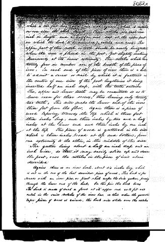
Page 3.
which is two feet long, and one inch square, which is notched on one side the whole length. These notches are each one inch in length and a half an inch deep at the upper part on which the hook (to be described) catches and rests. The upper part of this notch or tooth should be nearly horizontal when the iron is placed in the post, yet slightly inclining downward at its inner extremity. The notches which are twenty four in number are of the breadth of the piece of iron. In each end of the piece of iron there is a hole to admit a screw or nail by which it is fastened in the centre of one side of the post lengthwise it being inserted half an inch deep, with the teeth outside. The upper and lower teeth may be omitted so as to leave room for these screws, thus leaving only twenty two teeth. This will make the lower end of the iron three feet from the floor. Again there is a piece of wood tapering towards the top which is three feet three inches long, and three inches by two and a half inches at the lower end and three inches by one inch at the top. This piece of wood is guttered in the side which is three inches broad at top and bottom, from one extremity to the other, in the middle of the side the gutter being about a half an inch deep and an inch wide, so that it may easily slide up and down the post, over the notches in the piece of iron above described.
Again there is an iron hook, about six inches long, which is set in the end of the last described piece of wood. This hook is fastened with an iron pin, or pivot which cooper, the said gutter, passing through the lower end of the hook. On this pin the hook turns. The hook is made of such a form at its upper end as to fit into notch in the same notches of the iron bar, so that when the former taper piece of wood is removed, this hook will slide over the notches
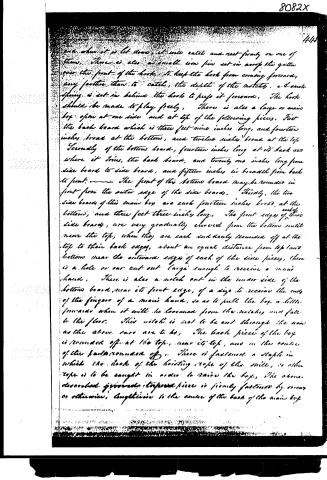
Page 4.
and when it is let down, it will catch and rest firmly on one of them. There is also a small iron pin set in across the gutter over the front of the hook, to keep the hook from coming forward, any farther than to catch, the depth of the notches. A small spring is set in behind the hook to keep it forward. The hook should be made to play freely. There is also a large or main box open at one side and at top of the following pieces. First the back board which is three feet nine inches long, and fourteen inches broad at the bottom, and twelve inches broad at the top. Secondly of the bottom board, fourteen inches long at its back and where it joins, the back board, and twenty one inches long from side board to side board, and fifteen inches in breadth from back to front. The front of this bottom board may be rounded in front from the outer edge of the side boards. Thirdly, the two side boards of this main box are each fourteen inches broad at the bottom, and three feet three inches long. The front edge of these side boards, are very gradually curved from the bottom until near the top, when they are each suddenly rounded off at the top to their back edge, about an equal distance from top and bottom near the outward edge of each of the side pieces, there is a hole or our cut out large enough to receive a man's hand. There is also a notch cut in the under side of the bottom board, near its front edge, of a size to receive the end of the fingers of a man's hand, so as to pull the box a little forward when it will be loosened from the notches and fall to the floor. This notch is not to be cut through the wood as the above ones are to be. The back piece of the box is rounded off at the top, near its top, and in the centre of the back rounded off. There is fastened a staple in which the hook of the hoisting rope of the mill, or other rope is to be caught in order to raise the box. The above described grooved topmost piece is firmly fastened by screws or otherwise, lengthwise to the centre of the back of the main box.
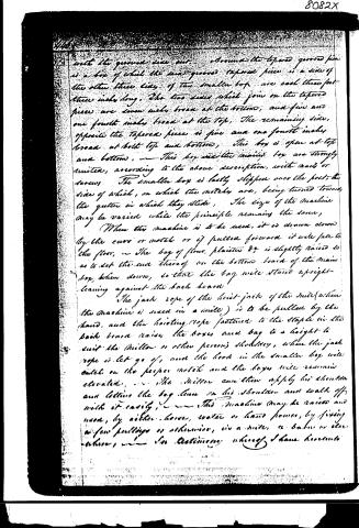
Page 5.
with the grooved side out. Around the tapered grooved pin is a box of which the two grooved tapered pieces is a side of the other three sides of the smaller box are each three feet three inches long. The two sides which join on the tapered pieces are seven inches broad at the bottom, and five and one fourth inches broad at the top. The remaining side, opposite the tapered pieces is five and one fourth inches broad at both top and bottom. This box is open at top and bottom. This box and the smaller box are strongly united, according to the above description, with nails or screws. The smaller box is lastly slipped over the post, the side of which, on which the notches are, being turned towards the gutter in which they slide. The size of the machine may be varied while the principle remains the same.
When this machine is to be used, it is drawn down by the cars or notch or if pulled forward it will fall to the floor. The bag of flour, plaster &c. is slightly raised so as to set the end thereof on the bottom board of the main box, when down, so that the bag will stand upright leaning against the back board.
The jack rope of the hoist-jack of the mill (when the machine is used in a mill) is to be pulled by the hand, and the hoisting rope fastened to the staple in the back board raises the boxes and bag to a height to suit the miller or other person's shoulder, when the jack rope is let go of, and the hook in the smaller box will catch on the proper notch and the boxes will remain elevated. The miller can then apply his shoulder and letting the bag lean on his shoulder and walk off with it easily. This machine may be raised and used, by either horse, water or hand power, by fixing a few pulleys or otherwise, in a mill, or barn or elsewhere.
I am, etc.
John B. Gage
Page 6.
8082X
447.
hereunto set my hand this fifteenth day of February, Anno Domini, one thousand eight hundred and thirty four,
Witness
E. Bradford Todd
John Detwiler
1584 No.
Olm Kinsman
Drawing
C.P.
Ck. 41.
Published accounts: journal notice
Notice in the monthly list of patents
Journal of the Franklin Institute, new ser., vol. 14 (1834), p. 245 · View the page
These bridle bits are to be made by twisting wire together, so as to form the several parts. 47. For a Machine to Raise Bags of Grain or Flour, for Shouldering; John Kinman, Hartley, Union county, Pennsylvania, March 15.
About this record
- Patentee
- DATAMP
- Date
- the Name and Date index of patents, DATAMP, USPTO records
- Invention
- DATAMP
- Listed in
- the Name and Date index of patents, DATAMP, USPTO records, Jim Shaw's X-patent list, the Journal of the Franklin Institute, Burke's List of Patents (1847)
- Burke's 1847 Patent Office list gives the same patent.