

Drawings and documents
National Archives restored drawings: drawing
Jeremy W. Bliss' Patent Drawing for a Mortising Machine


National Archives, Restored Patent Drawings (Record Group 241) · Full-size scan at the National Archives · Catalog record
Show the text on the drawing Hide (155 words)
Words on the drawing as machine-read by the National Archives; not checked. Useful mainly for searching.
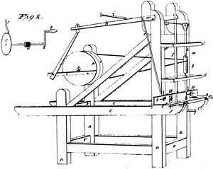
Sheet 1. 144. WOOD WORKING MACHINES. / Mortising, Chisel Cutters. / #2 / CLASSIFICATION / 8100-X / DIVISION. / JEREMY W BLISS. / MORTISING MACHINE. / Patented 20th Mar 1834. / Fig 1. / Fig 2. / References. / aa the posts. it girths g'i / c.c. bed pieceees dderosspieces / c moovable carriage / grove in / of / cross prece with lip / h mortining lever / bit lever / quare shaft with chisel / round shaft with lit / 7 whirl with pin / m grove in shaft k / button or washer / double pulley / 70 / single pulley / Q preeeof wood connected the arber of lever h / 7° arm connected the ratchet wheel / Patent Office I'June 1838 / ratehet which / Made under the duection of the Commisioner of / Z crunk и pinion connected 702 2h a / rack on the under side of the carriage / Patents in conformity, with act 3 March 1837 / v hold pasts. / w modge / thumb severos / MLSMorth / pague / Commiproner of Patents
Sheet 2. 143. WOOD WORKING. / 2. GENERAL WORK MACHINES. / 173 Mortising. / DIV
USPTO scan
The patent as scanned by the USPTO
-
 Page 1
-
 Page 2
-
 Page 3
-
 Page 4
-
 Page 5
-
 Page 6


U.S. Patent and Trademark Office · Google Patents
Show the transcription Hide (1,403 words)
Machine transcription (LightOnOCR) of the pages as scanned by the USPTO, most of them the handwritten copies made when the records were restored after the 1836 fire. Not checked; it can misread handwriting, so compare it with the scan.
Page 1.
8100x
2 Sheets-Sheet 1.
J. W. Bliss,
Mortising Machine.
Patented Mar. 20, 1834.
Fig 1.
Fig 2.
Page 2.
8100X
2 Sheets-Sheet 2.
J. W. Bliss,
Mortising Machine.
Patented Mar. 20, 1834.

AM. PHOTO-LITHO. CO. N.Y. (OSBORNE'S PROCESS)
Page 3.
3/20/1834 8100X
Mar 20, 1834
Jeremy Wells Blifs, of Somers, Conn.
Letters Patent
The Schedule referred to in these Letters Patent, and making part of the same containing a description in the words of the said Jeremy Wells Blifs himself, of his improvement in mortising timber by machinery.
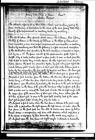
To all to whom these presents shall come; Be it known that I Jeremy W. Blifs, of Somers, in the County of Tolland in the State of Connecticut have invented, a new and useful improvement and invention in mortising timber by machinery, and that the following is a full and exact description of the construction and operation of the said machine as invented or improved by me — 1st. The frame consists of two perpendicular posts 6 feet in length, 3 by 4 inches, called front or face posts — 2 rear or back posts; the left 4 feet 10 inches long, 4 inches square, the other 3 feet and 1 inch long 4 1/2 inches square; the posts are connected together by girts, 2 long girts 3 feet and 1 inch between joints 3 inches by 2 1/2; 3 short girts 12 1/2 inches between joints 3 inches by two connecting the face posts by mortises and tenons — the lower girts 6 inches from the bottom, the 2nd tier of girts enter the posts 23 1/2 inches from the bottom — the 3rd short girt in front enters the posts 4 feet 10 inches from the bottom; the two rear short girts are 10 1/2 inches long — 2nd. Two bed pieces 5 feet 8 inches long 4 inches by three secured to the frame upon the outside, by matching the bed pieces to the posts with joint bolts inserted in the tenons of the girts — the bed pieces extend in front of the face posts 9 inches and in rear of the back posts 15 inches, 4 tie at right angles, with the upper face of the second tier of short girts, 2 long braces extend from the 2nd tier of short girts in rear to the front posts, directly back of the upper short girt in front, 4 feet 3 inches long 3 by 1 1/2 inches — 3rd. In front 2 feet 11 inches above the bed pieces, is screwed to the posts a cross piece with 2 perforations, the right square, the left round — 10 inches above the bed pieces in the front posts are two slits to receive and secure by bolt & thumb screws a corresponding cross piece with shoulders, which cross piece is to be raised or depressed by said screws so, as the work may require — 4th. In front upon the bed pieces, at right angles is placed a movable
Page 4.
carriage 4 inches wide 3 feet long 2 inches thick, with a lip 1/4 an inch wide to run in a groove cut in the front of the post, to prevent the carriage rising up. The main part of the carriage shouldering against the post. The carriage has a groove in front the whole length, 1/4 secured to the bed pieces, by a crofs piece in front with a lip inserted in the groove and made fast to the bed pieces by screws & bolts; directly above the carriage & resting thereon is placed a moveable gage to regulate the shoulder of the work of the same length as the carriage 1/4 of an inch thick with keys or wedges affixed to the back of said gage having horizontal slits therein & moving parallel with the carriage on bolts secured in the post by thumb screws —
52. On the back part of the front post, directly above the braces are affixed and secured by bolts two pieces of wood, one foot long 3 inches square with a hole in each 4 inches from top to receive tenons of a rail 1/4 inch square which passes from piece to piece one through the operating lever, attached to the mortising shaft 8 inches from the end of the lever 8 inches from the top of said pieces on the back part thereof is affixed, a crofs piece 2 inches by 1, with a tenon thereon 3 inches long 1 inch wide and 1/4 an inch thick and 1/4 inch from the inside of the piece attached to the left post, which tenon passes through the lever which raises & depresses the shaft, connected with the spiral bit.
67. A shaft 3 feet 8 inches long 1/4 inch square with a chisel for mortising 6 inches long inserted in the end & secured with a screw or wedges also a round shaft 1/4 inch in diameter with a groove 3 1/2 feet in length with a moveable whirl 3 inches in diameter 4 1/2 inches long with a spin or pin passing to the centre of said whirl and moving in said groove which can be raised or lowered on the shaft by screws, in the end of said shaft a spiral or conical bit is inserted 6 inches long and of any required dimensions 4 inches from the top of the round shaft and thereon is placed a button or washer 2 1/2 inches in diameter 4 3 inches long which may be raised or lowered on the shaft with a pin or screw, the button or washer having a groove near the upper part in which to receive a lever by which the bit may be raised & depressed while in operation —
71. A lever with a ball at one end 2 feet 6 inches long with a mortice 9 inches from the other end passing on to the tenon in the crofs piece which
Page 5.
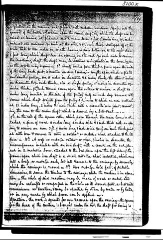
(i) flatted at the mortice end & fixed with metallic substance. It passes into the groove of the button or washer upon the round shaft by which the shaft can be raised or lowered at pleasure. Also a main lever 4 feet 5 inches long 3½ inches wide at one end and 1½ inch at the other & 1½ inch thick, scolloped off at the wide end to two inches in width having a piece bolted on to the right side 1 foot long, which shaft has an opening in the end 1½ inch wide to receive the morticing shaft; the shaft may be shortened or lengthened in the lever by pins as the work may require. 8½. Twenty inches from the bed piece, upon the inside of the long back post, is inserted an axis 6 inches in length, upon which is placed one double pulley, one 18 inches in diameter & 2 inches thick, the other 11 inches in diameter & 1½ inch thick, also a single pulley 18 inches in diameter 2½ inches thick. 1½ inch turned down upon the outside to receive a shaft 20 inches long inserted in the side of the pulley, half an inch deep & secured with screws, which shaft projects from the pulley 2½ inches, to which an arm is attached 21 inches long, 2 inches & 1 inch thick, with a moveable iron joint, connecting the arm to the main shaft, which is secured by a bolt & nut. 9½ on the end of the square roller, which passes through the main lever, is attached a piece of wood 4 inches long, 2 inches wide & 1 inch thick with an opening to receive an arm 3 ft. 9 inches long 1 inch wide & ¼ of an inch thick, pointed with iron & curved to enter a ratchet or metallic wheel attached to the bed piece — 10½. A croft or metallic ratchet or wheel, 3 inches in diameter, the circumference indented with an iron shaft, with a crank on the end, placed in 2 metallic boxes, attached to the bed piece upon the left side of the frame, upon which iron shaft is a small metallic wheel indented, which runs into a croft or metallic rack, let into & secured to the carriage by screws, by which the carriage is moved — 11½. Two metallic hold fasts, of suitable dimensions, to secure the timber to the carriage, while the machine is in operation. The whole of said machine may be made of wood or metal and may be enlarged or compressed in the whole or its several parts, as best suits convenience or location, & may be operated by steam by water or by hand, or in any mode by which power can be applied.
Operation. The work is squared for use & secured upon the carriage, the square for the head of the mortice is brought under the bit, the shaft for boring is
Published accounts: journal notice
Notice in the monthly list of patents, with remarks
Journal of the Franklin Institute, new ser., vol. 14 (1834), p. 251 · View the page
66. For a Mortising Machine; Jeremy W. Bliss, Somers, Tolland county, Connecticut, March 20.
Remarks. This machine is described with a minute account of the measurement of its different parts, and is represented in the drawing with sufficient clearness, but there is no claim made to the general arrangement, or to any of its individual parts, whilst, as machines for mortising are numerous, and as the mode of boring to commence the mortise, and of operating with the chisel, are very similar in most of them, it becomes important to the patentee to be very specific in pointing out what he claims as new. In this machine the stuff to be mortised is placed upon a suitable bed, so that it may be bored by a bit at the lower end of a revolving, vertical shaft; the piece is then so shifted as to bring the part to be mortised under the chisel, and the band thrown from the whirl of the boring on to that of the mortising part, which, by a crank motion, operating upon a lever, works the chisel up and down.
DATAMP: illustration
Illustrations from DATAMP

DATAMP (Directory of American Tool and Machinery Patents), via the Internet Archive · Archived DATAMP page
About this record
- Patentee
- DATAMP
- Date
- the Name and Date index of patents, DATAMP, USPTO records
- Invention
- DATAMP
- Listed in
- the Name and Date index of patents, DATAMP, USPTO records, Jim Shaw's X-patent list, the Journal of the Franklin Institute, Burke's List of Patents (1847)
- Burke's 1847 Patent Office list gives the same patent.