

Drawings and documents
National Archives restored drawings: drawing
Melville Otis' Patent Drawing for a Spring Nipper

National Archives, Restored Patent Drawings (Record Group 241) · Full-size scan at the National Archives · Catalog record
Show the text on the drawing Hide (147 words)
Words on the drawing as machine-read by the National Archives; not checked. Useful mainly for searching.
85. METAL WORKING, / Cut Nail M'k'g. / CLASSIFICATION / 8103-X / DIV ISION. / Modville Olis / Spring Hipper. / in the Machine for making but nails at one operation / Patented 20 March 1834 + / Re ferences. / A nipper post / B The guard on the nipper urm which may be open at bottom. / c The modified old upper so and to assist by its inclined / plane the spring hipper in turning the mail / D The spring ripper. / E The wedge-Key. / I'. The nipper-arm. / FL The pivoted nipper to the arm a little distance from the / guard / M The end of nippers where they perform the office of / turning the nail as described in the specification. / G.delt JB. delt / Patent Office / Meade under the direction of the Commissioner / of Patents in conformity with act. 3d March 1837 / Commifriener of Patents
USPTO scan
The patent as scanned by the USPTO
-
 Page 1
-
 Page 2
-
 Page 3
-
 Page 4
-
 Page 5
-
 Page 6
-
 Page 7
-
 Page 8
-
 Page 9
-
 Page 10
-
 Page 11


U.S. Patent and Trademark Office · Google Patents
Show the transcription Hide (4,469 words)
Machine transcription (LightOnOCR) of the pages as scanned by the USPTO, most of them the handwritten copies made when the records were restored after the 1836 fire. Not checked; it can misread handwriting, so compare it with the scan.
Page 1.
8103X
M. Otis
Making Cut-Nails,
Patented Mar. 20, 1834.
Page 2.
Mar. 20, 1894
Melville Otis, East Bridgewater, U.S.A.
Letters Patent.
The Schedule referred to in these Letters Patent and making a part of the same, containing a description in the words of the said Melville Otis, himself of his improvement in the machine for making but nails at one operation.
Be it known that I Melville Otis of East Bridgewater in the County of Plymouth and Commonwealth of Massachusetts, have invented, constituted, and applied to use a new and useful improvement in the machine for making cut nails at one operation, which machine and improvement are here described and specified as follows: viz:
The machine is made of cast iron, except where otherwise herein after mentioned, and consists of various complex parts called respectively the Bed frame and posts. The head block, the cutting saw, the heading lever, the gripping levers, the spindle, the crank staff, the balance wheel, the lifter and the spring lifter. The Bed frame is the foundation of the machine and supports all the other parts. It is of a regular form, and consists of outside sills and 5 external and one internal right angle. The lengths of the sills, beginning at the front, on which the head block stands and going round at the left are successively as follows to wit, 25-28-17-13 3/8-8 and 11 3/4 inches, and the thickness of the sills 3 inches, except the back sill which is 1, and the width 3 3/4 inches, except the front, which is 5, and the back one which is 3 inches. On the back side of the frame, there are two upright posts 18 inches high, 5 wide and too thick. The narrow sides of the posts are perpendicularly in a line with the back side of the 17 inch sill and their wide sides at a right angle with the same side and distant 1/2 an inch from its ends. Centrally in the upper end of each post, there is a cavity 3 3/4 inches deep and 3 3/4 wide, cut in 3 3/4 and 11 3/4 inch sills, there are two short posts and 7 inches high 3/4 wide and in thickness corresponding with the width of the sills. The head block, is an upright piece of iron rising from the
Page 3.
the front or 85 inch sill of the frame, and distant at its center 9 1/2 inches from the 88 inch sill. It is 6 1/2 inches long, 6 wide, and 4 1/4 high on its front side and on the opposite side next to the cutting saw 4 inches high to a cavity in the top of the block. This cavity is in the form of a long square and is two inches wide 1 1/4 deep, and extends from its opening next to the cutting saw 5 inches towards the opposite side. Within this cavity on the side next to the heading set is placed a cast steel gipping die 5 inches long 3 1/4 wide and 5/8 thick, having a groove in the end next to cutting saw, adapted to receive the thick end or head part of the nail, and on the opposite side of the cavity, a piece of wrought iron, faced with steel at the opening, called the back piece sufficiently wide and long with the die to fill the diameter of the cavity at the bottom. The steel end of the back piece on the lower part has a shoulder or notch in a line with the groove in the die into which and the groove in the die, the nail is brought to receive its head. The die and back piece are adjusted and kept in their places by means of two iron screws passing through the end of the block, one upon the end of the die, and the other on the end of the back piece, and by another screw through the side of the block upon the side of the die, immediately over the die and back piece. There is placed a steel cutting knife, resembling in form a plane iron, having its edge grooved a little to conform to the circular motion of the knife in the cutting saw. One side of the knife is fitted to a groove in the block, and the other on its upper part is beveled, by means of which and 3 screws 3 passing through the side of the block, at a right angle upon the beveled part of the knife and the other through the end of the block upon the end of the end of the knife that instrument is held firmly in its place, and the relative position of its cutting edge with that of the knife in the cutting saw regulated, as the knife is thinnest on its beveled side, and from there it gradually increases in thickness through its upper surface to the opposite side, its cutting edge is not exactly in a horizontal line, but from a slightly inclined plane from its highest part nearest the heading set. On the top of the head block at the right of the right of the knife, there is a wrought iron plate called a guard, 5 inches long 1 1/4 wide in the center, and tapering from there to 1/2 an inch at each end, having on the sides of the
Page 4.
in the block of the required size, made to receive an instrument called the spring gauge. The groove opens into the cavity of the block and terminates in the upper part at a small hole, in a line with the groove through the top of the block. An iron or steel bolt about 1 inch and 1/4 long is inserted and fastened in the hole, having at its lower end, when it enters the groove, a mortise, into which the upper and flattened end of the spring gauge is inserted and pinned horizontally, so as to form there a movable joint. The gauge, made of steel, is 1/4 an inch wide and 3/16 thick. In the line of its length, it corresponds in form with the back side of the knife and its bevelled edges. Its lower end extends a little below the edge of the knife, and is true even, having its front side nearly in a line with the upright front side of the knife. With this gauge are connected a spring, secured on the back side of the block, and a small cylindrical rod, which extends from the spring through a hole in the block, directly upon the back of the gauge. When the machine is at work, as soon as the nail is set, the spring presses the rod against the gauge, by which means the gauge is made to bear against the nail and hold it securely till it is brought down and carried into the die and shoulder of the back piece.
The leading lever, has a plate nearly horizontal when at rest 3 inches long, 1/4 wide and 1/8 thick, terminating at each end within its length on the side next to the head block, in a projection or arm at a right angle with the plate, 1 inch long, 3/8 wide and 1/8 thick. The ends of the arms are circular and on their lower sides extend so far below the line of the under side of the plate, as to have a vertical diameter of 3/4 inches. Through the centre of each end, a judg or screw passes horizontally, one into a socket in the front side of the head block 1/2 of an inch above the line of its junction with the bed frame, and the other into a socket, in the semicircular projection from the upper side of the middle sill of the bed frame 1/2 of an inch above the line between the projection and sill. The centres are made fast and adjusted in the same way as those on the cutting saw shaft, and are so placed in relation to the parts of the machine, as that a line drawn perpendicularly from a point between the leading set and the guiding dies when brought together will fall upon and intersect a right line between them entirely in the
Page 5.
The plate rests to the knife a perpendicular piece of faced steel extending to the rim of the plate next the cutting saw—1 1/2 inch square and 3/4 of an inch thick. This guard is screwed through the entire of the plate to the block, and is designed to regulate the length of that part of the nail which is to be left without the die and which is to form the head of the nail. The cutting saw, as called, perhaps, from the resemblance of its motion to that of the human saw, has an irregular horizontal shaft connected at a right angle with the arm or lever, from which it receives its motion. The shaft at each end is supported by and turns upon a wrought iron or steel guage or centre, which passes horizontally through one of the short posts in the bed frame, at the same height from the frame as the groove in the gifting dies, and enters a socket made to receive it in the end of the shaft. The centres are pressed into the sockets and retained therein by screws; one operating vertically through the top of the post upon the side of the centre and the other through a guard and thence upon the end of the centre. On the upper side of the shaft at about 2/3 of its length from the lever and opposite to the head block, a block rises about 7 inches above the axis of motion, and immediately over that part of the shaft which has a recess upwards to give room for a portion of the gifting lever. This block has on its front side a cavity resembling in form that in the head block, within which is placed a moving cutting knife of the same general form with that in the head block, about 5/8 of an inch thick and beveled on the lower part of the back side for about 3/4 of an inch to the cutting edge. This edge which is on a horizontal line, is about 1/8 of an inch thick, and forms a slightly acute angle with the front side of the knife. This knife like the stationary one is made fast in its place, by means of a groove in one side of the block, and screws upon the side of the knife on the other. There is also a screw through the top of the block upon the upper end of the knife, to press it downwards, as occasion may require. For the purpose of adjusting properly the cutting edge of this knife with that of the knife in the head block there are two screws, which pass through the lower part of the block from the back side, and screw in the lower and back part of the knife. Each of the knives has a groove in the
Page 6.
on the upper side of the plate and at a right angle with it is that part of the heading lever, which may be called the base of the same. It extends from its lower part from the outer edge of the plate to a point one inch distant from the inner edge below which point and edge, it projects downwards to the under side of the plate. It is 3 inches thick, and 3½ high from its lower side and letter in the head block and cutting saw and the point is nearly over the center of the plate, where it rises into a circular arm. The line of the under side of the arm is horizontal to the extent of one inch from its end, and then a quarter circle described by the sweep of a 1 inch radius from a center in a line with the upper surface of the plate and ½ inches from its outer edge. The circular line of its upper side is formed by the sweep of a 6 inch radius from a center 3 inches from the same edge of the plate. That part of the Machine, which presses against the nail, when engaged by the dies, and forms the head, is a cylindrical bar of steel 5 inches long and 1 inch diameter, and is called the heading set. This bar is inserted in a groove or bed made for it in upper side of the base of the lever, and extending a little into the circular arm. It is moved and regulated by means of a staple passing over the bar, and through holes drilled in the base of the lever and plate, to the under side, and then riveted and by a screw through the top of the staple upon the upper side of the set and another through the lower part of the circular arm, upon its end. The circular arm of the lever is connected, by means of a toggle with a projection from the shaft of the cutting saw, made in a line with the lever of the cutting saw, or with what may be considered a part of that lever extended beyond the shaft. This toggle is made of bell metal, and is 3 inches long, 1 inch diameter and has semi globular ends, one end of it is set in a socket in the lower side of the circular arm of the lever near its end and the other in a socket in the upper side of the projection. The arm and projection are also connected by means of a small iron rod or wire which passes from the end of the latter and hooks into a notch in the top and near the end of the former. This wire is designed to bring the heading lever up from any cause its weight should be insufficient for that purpose. The lifting lever has a shaft placed horizontally to
Page 7.
between the front and middle sill of the head frame (its lower side 3/4 of an inch above the lower side of the sill) moving on guides or centers, through the 38 1/4 inch sill of the frame. This shaft is 3 inches thick throughout and 3 inches wide at each end. From the one next to the 38 inch sill, it gradually increases in width until at the distance of 8 1/2 inches it is 4 inches wider. It continues of this increased width for 3 1/2 inches, and thence to the other end, a distance of 11 inches, it gradually decreases to 3 inches. The form of the shaft is such that, that portion of its side next to the head block, whose length is 8 1/2 inches, is parallel with, back of, and 1/4 inch distant from a sight line between the centers. The base of the lever so called, is 10, and coincides with that part of the shaft which is 3 1/2 inches wide. Its height to its top under the recess in the shaft of the cutting saw, is in front 5 1/2 inches, and the line of its top to the arm of the lever the same. The back side of the base to the height of two inches is perpendicular and then, in the form of an arc, of a circle whose radius is 12 inches; the arc terminating at a point perpendicularly under the junction of the top line of the base with the arm of the lever and at 3 inches distance below it. On the side of the base next to the head lever, there is a rabbit or bed 1 inch deep and wide and 7 long into which is placed a steel gripping die. In the end of the die next to the head block, there is a groove to receive the nail corresponding with that in the stationary die. The die is held in place by a wrought iron bolt, which passes over the top of the die and down its outside in the form of a hook and then horizontally through the base of the lever, immediately under the die, to the opposite side, and is there keyed. It is moved forward as occasion may require by a screw upon its end. The arm of the lever to its junction with the base is, on the front side, 18 and on its back side, 19 1/2 inches long. It is 2 1/2 inches thick throughout, 4 inches wide at its junction and 1 1/4 at the top, and is so placed relatively to its base, as that when raised to its greatest extent by the arm, the die in the base will meet the die in the head block in a horizontal line.
The spindle, is a horizontal shaft, moving and turning in the centers
Page 8.
81034
969.
leavices of the two upright long posts 35 inches long and 2 1/2 square within the posts. The parts of the spindle, which turn on the cavities or necks are cylindrical, and are 3 1/2 inches long and 3 in diameter. On and near that end of the spindle, which is on the same side of the Machine as the 1 3/4 inch sill, there is an arm at a right angle with the spindle 7 inches long (1 1/2 from the centre of the spindle in one direction, and 2 1/2 in the opposite direction) 1 1/2 inch thick and 3 wide at the lower end, from whence it gradually diminishes to two inches at the upper end. At the distance of 3 1/2 inches from the end of the longer portion of the arm and through the centre, there, of its wide side, an iron bolt 3 1/2 inches long and 3/4 inch in diameter is inserted one end of which passes into an orifice made for the purpose between the boxes, in the upper end of the crank staff. The bolt is made fast by a screw upon its side through the end of the arm. At 5 inches distant from the neck of the spindle nearest to the aforesaid arm is placed the cam of the gifting lever. This cam may be constructed by the following rule, to wit: With a three inch radius describe a circle, an arc of 90 degrees of this circle will form one portion of the cam. From a point in the centre of the end of this arc, extends a line through the centre of the circle, and one inch and a half beyond. Then if a circle be formed, so as to pass through the end of the arc, and the end of the extended line it will exhibit the form of the other and larger portion of the cam. When the spindle turns, supposing the bolt in the aforesaid arm to be directly above the axis of motion, the bolt ascends towards the heading lever and when it has passed 1/2 an inch below a line horizontal to the axis of motion, the end of the gifting lever is raised by the cam on the spindle to its greatest extent, at 3 inches distant from this cam is the upper cam 1 1/2 inch thick. It is so formed as that in operating on other parts of the Machine hereafter to be described, the spring upper is applied to the nail as soon as the knife has carried it down, to its lowest point, and holds until it is gifting by the dies.
The crank staff, is made of wrought iron, is 18 1/2 inches long, 1 1/2 thick and 1 1/2 wide to within 1 1/2 inches of the ends where it is 3 1/2 inches wide and 1 1/4 thick within each end there is a cavity 3 1/2 inches long
Page 9.
8103X
long and 1¼ wide, into which 3 composition boxes are placed. These boxes have a bed between them into which on the upper end of the staff the bolt from the arm of the spindle is inserted and on the lower end a similar bolt from the lever of the cutting saw.
The balance wheel is 30 inches in diameter, its rim 5 inches broad and 1½ thick. It has a hub 6 inches in diameter and 3 thick, and 4 arms each 3 inches wide at the junction with the hub and 1¾ at the junction with the rim. The wheel is placed on the outer side of one of the high posts ½ an inch distant from it and hangs upon, and is confined on, one end of the spindle, which is made to pass through its hub, and finishes beyond it into a pulley.
The nipper resembles in form a cane iron. Its post is on the 28 inch side of the bed frame, near the shaft post, through which a centre of the cutting saw passes and on that side of it nearest to the front side of the frame. The bottom of the post has a conical point, which enters and moves in a conical socket in the side and its top a conical socket into which a conical screw enters through one end of a cap, which at the other end is fastened on the top of the short post. The arm of the nipper extends horizontally from its insertion in its post to the spring gauge leaving nearly sufficient room between them to admit of their moving freely by each other without touching. It is made of steel and is one inch wide at its insertion and gradually tapers to ¾ an inch next to the gauge. Its thickness is ⅜ of an inch. The upper side of the arm next to the gauge has a perpendicular projection upwards ¾ an inch square and ⅜ of an inch thick. The nipper arm is so placed in its post, as that this projecting part of it may pass directly under the small prominent part of the back piece. The nipper is moved by means of a small iron rod or wire, whose ends are in the form of a tenon inserted loosely one into the nipper arm at about 3 inches from the nipper post, and the other into the lower end of the nipper lever. The nipper lever is ¾ of an inch square and extends perpendicularly from the back side of the spindle where it is in contact.
Page 10.
8103X
conducted with the nipper arm, to the upper surface, without touching of the back side of the bed frame. Its centre of motion is at 4 inches distance from the top of the lever, where it is moved at a right angle by a bar ½ of an inch square, extending from one high post to the other. The lever and bar are supported by and turn upon conically pointed screws through the sides of the post passing into conical sockets in the ends of the bar. For the purpose of bringing back the nipper after it has been carried forward by the motion of its arm, a wire may be attached to the nipper arm, and extended under the cutting jaw to a spring fastened to the high post near the balance wheel.
The Spring Nipper, consists of a straight bar of steel, inserted and leaved at one end in the nipper post, directly over the nipper arm, and extending from thence horizontally to the projecting part of the nipper. At its insertion it is ½ of an inch square and from thence gradually enlarges to ¾ of an inch at the opposite end. At this end, it should be so far forward of the nipper as to perform its office of turning the nail into the die and shoulder of the back piece, before the projecting part of the nipper comes in contact with the nail.
If preferred the nail spring nipper may be attached to the broad side of the nipper arm near the nipper post by screws or rivets, through a part of the spring nipper, sufficiently enlarged to receive them and extended from thence nearly horizontally to the end of the nipper, at the same distance forward of it as was required in the preceding mode. So much of the end of the spring nipper on its upper corners next to the projecting part of the nipper as is usual in length to that projecting part, is beveled. When this mode of placing the spring nipper is adopted, the projecting part of the nipper is bent forward to conform to the beveled corners of the spring nipper. Should the spring nipper from any cause meet with an unusual resistance in turning the nail, this bent part of the nipper is designed to pivot on the beveled corners of the spring nipper, and so change the direction of its motion as to cause it to perform its office properly. In both modes the relative position of the nipper
Page 11.
B103x
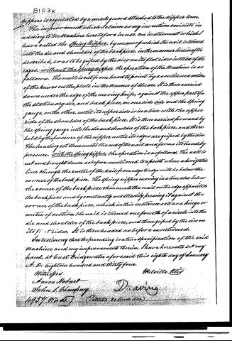
Nippers unregulated by a small guard attached to the nippers arm.
The improvement which I claim as my invention consists in adding to the Machine heretofore in use, an instrument which I have called the Spring Nipper, by means of which the nail is turned into the die and shoulder of the back piece, in the manner herein after described, so as to be gripped by the dies on its flat sides instead of the edges. Without the Spring Nipper, the operation of the Machine is as follows. The nail is cut from head to point by a continued action of the knives on the plate in the manner of shears. It is then carried down under the edge of the moving knife, against the upper part of the stationary die, and back piece, on one side side and the Spring gauge, on the other, until its upper side is in a line with the upper side of the shoulder of the back piece. It is then carried forward by the Spring gauge into the die and shoulder of the back piece, and there held by the pressure of the nipper until its edges are gripped by the dies. The heading set then meets the end of the nail and forms its head by pressure. With the Spring Nipper, the operation is as follows. The nail is cut and brought down as before mentioned to a point where a horizontal line through the centre of the nail from edge to edge will be below the corner of the back piece. The Spring Nipper moving in a line also below the corner of the back piece then meets the nail on the edge opposite to the back piece and by constantly and steadily pressing it against the corner of the back piece, which in this instance acts as a hinge or centre of motion, the nail is turned one fourth of a circle into the die and shoulder of the back piece, and then gripped by the dies on its flat sides. It is then headed as before mentioned.
In testimony that the preceding is a true specification of the said Machine and my improvement therein, I have hereunto set my hand, at East Bridgewater aforesaid this eighth day of January A.D. eighteen hundred and thirty four.
Witnesses
Aaron Hobart
John J. Blanford
Melville Otis
Drawing
4457 No. 10 (Patent Office 1834)
Published accounts: journal notice
Notice in the monthly list of patents, with remarks
Journal of the Franklin Institute, new ser., vol. 14 (1834), p. 250 · View the page
65. For a Nail Machine; Melville Otis, East Bridgewater, Plymouth county, Massachusetts, March 20.
Remarks. This is a machine for making and heading cut nails, and intended as an improvement upon Reed's machine for cutting and heading. The whole machine is described, but the only thing claimed is the "adding to the machine heretofore in use, an instrument called the spring nipper, by means of which the nail is turned into the die, so as to be griped by the dies on its flat side, instead of the edges." The manner of constructing and of operating with the spring nipper, is particularly described; but for a clear understanding of these, the drawings would be necessary.
DATAMP: illustration
Illustrations from DATAMP


DATAMP (Directory of American Tool and Machinery Patents), via the Internet Archive · Archived DATAMP page
About this record
- Patentee
- DATAMP
- Date
- DATAMP
- Invention
- DATAMP
- Listed in
- the Name and Date index of patents, DATAMP, USPTO records, Jim Shaw's X-patent list, the Journal of the Franklin Institute
- The sources give different dates; the date shown is the one most of them agree on.
- The date conflict was settled by Burke's 1847 list.
- The Franklin Institute's journal confirms the date shown.