

Drawings and documents
National Archives restored drawings: drawing
Reuben Daniel's Patent Drawing for a Shearing Machine


National Archives, Restored Patent Drawings (Record Group 241) · Full-size scan at the National Archives · Catalog record
Show the text on the drawing Hide (52 words)
Words on the drawing as machine-read by the National Archives; not checked. Useful mainly for searching.
Sheet 1. CLASSIFICATION / 8191x / DIVISION. / the / BAONDAS / BANAOA / OlA / 110 / he / 10
Sheet 2. Old / CLASSIFICATION / 8191 X / ISION. / Q 3
Sheet 3. REUBEN DANIELS. / SHEARING MACHINE. / CLOTH. / [37] Shearing. / N° 2. / 618 / Fig 1. / Patented 13 May 183 / $11 / CLASSIFICATION / Reissued 22 Aug 18's / 8191x / 8191x / 7834 / DIVISION. / So / Fig 2. / Fig / 3.
USPTO scan
The patent as scanned by the USPTO
-
 Page 1
-
 Page 2
-
 Page 3
-
 Page 4
-
 Page 5
-
 Page 6
-
 Page 7
-
 Page 8
-
 Page 9
-
 Page 10


U.S. Patent and Trademark Office · Google Patents
Show the transcription Hide (2,348 words)
Machine transcription (LightOnOCR) of the pages as scanned by the USPTO, most of them the handwritten copies made when the records were restored after the 1836 fire. Not checked; it can misread handwriting, so compare it with the scan.
Page 1.
8191x
R. Daniels.
Shearing Mach.
Patented May 13, 1834
Sheet 1. 3 Sheets.
Fig. 1.
Fig. 2.
Fig. 3. Fig. 4.
Page 2.
8191x
Sheet 2. 3 Sheets.
R. Daniels.
Shearing Mach.
Patented May 13, 1834.
No 1

Page 4.
5/13/1834 8191X
May 13, 1834 22
Reuben Daniels
Letters Patent
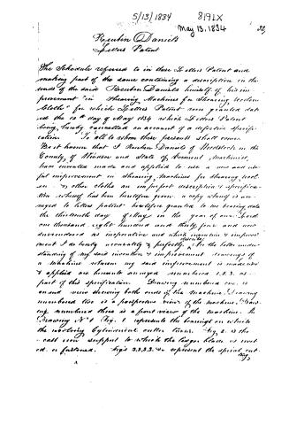
The Schedule referred to in these Letters Patent and making part of the same containing a description in the words of the said Reuben Daniels himself of his improvement "in Shearing Machines for Shearing Woolen Cloths" for which Letters Patent were granted dated the 13th day of May 1834 which Letters Patent being finally cancelled on account of a defective specification. To all to whom these presents shall come.
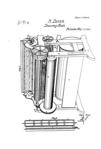
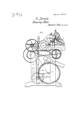
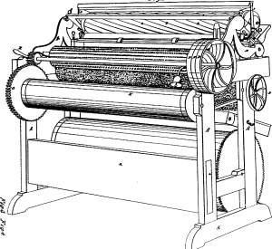
Be it known that I Reuben Daniels of Westfield in the County of Windsor and State of Vermont machinist, have invented made and applied to use a new and useful improvement in Shearing Machines for Shearing Woolen or other cloths an imperfect description & specification whereby has been heretofore given a copy whereby is annexed to letters patent heretofore granted to me bearing date the thirteenth day of May in the year of our Lord one thousand eight hundred and thirty four and now surrendered as infringing and which invention & improvement I do hereby unconditionally & perfectly describe & for the better understanding of my said invention & improvement drawings of a Machine wherein my said improvement is made and applied are hereunto annexed numbered 1, 2, 3, as part of this specification. Drawing numbered one is an end view showing both ends of the machine. Drawing numbered two is a perspective view of the machine. Drawing numbered three is a front view of the machine. In Drawing No. 1 Fig. 1 represents the bearings on which the rotating cylindrical cutter turns. Fig. 2 is the cast iron support to which the large blade is mounted or fastened. Figs 3, 3, 3, 3, 4 represent the spiral cutting
Page 5.
5/13/1834 8191x
28
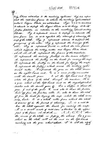
ting blades attached to the revolving cylinder Fig. 4, 4. represent the cast iron frame to which the revolving cylindrical cutter's ledger blades are attached. Figs. 5, 5, 5, 5, are screws to elevate or depress the ledger blades so as to bring it to its proper position in relation to the revolving spiral cutting blades. Fig. 6 represents screws to depress or elevate the iron frame 4, 4, so as to regulate the closeness of shearing the nap of the cloth. Fig. 7 represents stands to support the grooved of the roller. Fig. 9 represents the bearings of the roller. Fig. 10 represents pivots on which the iron frame which supports the rotary cutter and ledger blades turns. A, A, A, A, A, A, represent the frame of the machine. B represents the driving pulleys on the main shaft. C represents the pulley on the brush for raising the nap. D represents the pulley on the brush for laying the nap. E represents the pulley which drives the revolving cylindrical cutter. F represents the gear on the cloth drum on the right hand end. G is a cone pulley connected with the small gear. S at the left hand end to regulate the feed of the cloth through the machine. H is a gear wheel at the left hand end on the cog-shaft which meshes into the small gear G. I is a shipper to throw the gear F out of the gear H, and also to throw the friction levers off from the friction roller K, also to throw the cloth off from the brush for laying the nap while the cloth is running back. L is a cloth roller from which the cloth is drawn off in the process of shearing. M is a rest to bear the cloth against the brush for raising the nap. N is a scroll made of cast iron attached to the upper part of the frame 4, 4, 4, 4, 4, 4, 4, 4, …
Page 6.
5|13|1834 8191X
329.
back after it has passed the shears. This operation is performed by moving the gear O by means of the lever R, placed in a groove running around the gear O at the left hand end which gear O runs loose on the driving shaft while the cloth is in the process of shearing, after the whole roll has passed the shears, the bell gives an alarm and the attendant moves the lever R from right to left and the gear O connects with the stationary way on the driving shaft, and the motion of the cloth is arrested and the cloth again wound around the roll in readiness to be sheared a second time. (During the process of shearing) the motion of the cloth in passing the shears turns the cloth roll and the gear O being meshed into the gear P, the latter gear P turns like a loose pulley on the driving shaft. a, a, a, are ends of girts that go lengthwise of the frames. C is the brush for raising the nap. d is the brush for laying the nap. h, h, h, are screws to adjust the rolls M, V, C. K is a roll to tighten the cloth. L is a flanch on the roll M, to receive the screw b. In drawings numbered 2 and 3, the same letters and figures represent the same parts as in drawing numbered one. In drawing 4 and 5, m, m, m, is a support to receive the screw O, which passing through the nut P, and being turned by the crank A, moves the slide rest C, back and forward, on the other rest M. The several drawings 4 and 5 and fig. 1 in 4 and 5 are upon a scale of three inches to a foot. The machines represented in the drawings are adapted for shearing cloth from and to and but the form, construction, proportions and materials though may be some what varied at the discretion of the machinist and the construction and form of machines adapted for shearing from list to list will of course be somewhat different. But can
Page 7.
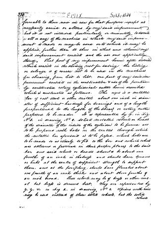
390 E191X 5/13/1834
formable to those now in use for that purpose except as necessarily varied or altered by my said improvement, but it is not intended particularly or minutely to describe all or any of the machines in which my said improvement is made or may be used or to which it may be applied, further than to show in what and wherein my said improvement consists and the use and application thereof. That part of my improvement herein after described which consists in the shearing rest for saving the livery or selvage is of course not to be used in the machines for shearing, from list to list. One part of my said improvement consists in the construction & use of the peculiarly constructed rotary cylindrical cutter herein described which is constructed as follows. The axis is a metallic bar of cast steel or other metal about one inch in diameter of sufficient hardness for bearings and of a length proportional to the length of the shears or rotary cutter proposed to be made. It is represented by y. in fig. No. 2. in drawing No. 2. Solid metallic wheels or heads of the diameter of the inside of the cylinder to be formed are to be prepared with holes in the centres through which the metallic bar aforesaid is to be passed, which holes are to be made so as closely to fit to the bar and which wheels are delivered or fastened in their proper places to the said bar, and said wheels or heads should be about one fourth of an inch in thickness and should have trunnions or hubs at the centre of sufficient strength to support them, and at the periphery, should have flanges about one fourth of an inch thick and about three fourths of an inch broad. These wheels may be of brass or other metal but brass is deemed best. They are represented by y, y, y. in fig. 2. in drawing No. 2. Spokes with arms may be used instead of these solid wheels, but the solid wheels
Page 8.
5/13/1834 8191X 23.
wheels are preferred on account of their superior firmness and stiffness in proportion to their weight. The number of these metallic heads, wheels or spindles ought to be such as that they may be about two or twelve inches apart from each other and of course must be more or less according to the length of the cylinder to be formed. The number however may be somewhat varied at discretion having regard to the firmness of the cylinder to be formed. One of these heads, wheels or spindles is to be placed at each end of the cylinder and when the metallic sheets having after mentioned are united to form the periphery of the cylinder, one of these heads, wheels or spindles should be put at each place where the sheets are united. On these heads, wheels or spindles a periphery made from sheets of tin or copper or other suitable metal bent & made into the form of a cylinder, with edges lapping over each other firmly, soldered or fastened together, so that the inner surface may conform exactly to the periphery of said heads, wheels, or to the rims of the spindles, is to be soldered or fastened firmly. Small strips of tin or other suitable metal, if about one half an inch in width leaving one of their edges bent up at right angles to the extent of about one-eighth of an inch, are to be firmly soldered or fastened by the widest part around the periphery of the cylinder thus formed, spirally like the blades of the rotary cutter now in use. The number of these strips is to be equal to the number of the cutting blades to be used, which may be from ten to twenty according to the diameter of the cylinder. The diameter of the cylinder may be from three to five inches or more. The back or even side of the cutting blades are to be soldered to the outside of the lips or upright edges of the strips of tin or other metal soldered or fastened.
Page 9.
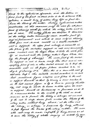
5/13/1834, 8191x
tense to the cylinder as aforesaid, and the bottom or lower part of the front or steel side is to be soldered to the cylinder, a small body of solder being left in front to brace the blade of the cutter. Rotary cylindrical cutters constructed in this manner may be used for all purposes of shearing cloth for which the rotary cutter now in use is used. The cutting blades are similar to those now in the rotary cutter commonly used. Another part of my improvement and which is used only in shearing cloth from end to end consists in a double metallic rest or support; the upper part whereof is moveable in the place of the metallic support or rest now commonly used under near the longer blade to hold the cloth firmly in contact with the rotary cutter's longer blade during the process of shearing. The under part of the metallic support or rest is made nearly like that now in use, excepting pieces of iron or other metal screwed on to keep the moveable rest in its proper place (marked x, x, in Fig. 2. of Drawing No. 2. Above this is a moveable rest of cast-iron, brass or other suitable metal marked, c, on said last mentioned figure adapted and fitted to the rest or support beneath so that by turning a screw marked, o, in the last named figure or by a lever or gearing the sliding rest may be made to move or slide upon the rest or support beneath it backwards or forwards so as to be accommodated to the width of the cloth in such manner as to permit the lifting or selvage at one end of the rest to drop down from under the blades of the rotary cutter without being sheared; at the other end the lifting or selvage is prevented by being allowed to pass beyond the blades of the rotary cutter. The moveable rest may be made capable of being moved so as to save the lifting of cloths varying in width by my
Page 10.
5/13/1834 819/X 339
ing, the sliding rest from right to left & left to right as occasion may require. The form of the movable rest is also shown by an end view in figure 344 in (Drawing numbered two. In the construction of the rotary cutter instead of a metallic sheet or sheets, a hollow cylinder may be cast from brass or other suitable metal & such strips of tin or other metal may be soldered thereon as aforesaid, and the blades may be soldered thereon as aforesaid but the metallic plate or plates is deemed preferable.
The sliding rest laps over the under rest at the top as represented in Figs 3 & 344 in (Drawing No. 2. so as to present an uniform surface for the cloth-straight & even. Although I have described the machinery and apparatus of the whole of a shearing machine, yet it is to be understood that I what I claim, and although I claim as new is as my invention & improvement is the construction of the rotary cutter with brass wheels or spindles and a metallic sheet or sheets as aforesaid, or of cast metal material as aforesaid, with the blades soldered thereon as aforesaid, and the use of rotary cutters so constructed & made in machines for the purpose of shearing woolen and other cloths, either from one to end or from left to right, and the construction & use of the sliding rest aforesaid, lapsing over aforesaid, in the machines for shearing cloth from end to end for the purpose of saving the liting or selvages. I do hereby that the above is a true specification of my said invention & improvement. I have hereunto set my hand this twenty ninth day of July eighteen hundred and thirty-four.
Witness
[Signature]
(Received Drawing 27000)
Drawing
[Signature]
Published accounts: journal notice
Notice in the monthly list of patents, with remarks
Journal of the Franklin Institute, new ser., vol. 14 (1834), p. 394 · View the page
12. For a Machine for Shearing Woollen Cloth; Reuben Daniel, Woodstock, Windsor county, Vermont, May 13.
Remarks. The specification of this machine commences by stating the things claimed by the patentee, which are the following: "First. I claim as my invention, the method of constructing the ledger blade, and the revolving cylinder, or bar, to which the twisted cutting blades are attached, of such a proper degree of stiffness as to permit of their being ground together with emery, or other hard pulverized substance, and oil. "Secondly. I claim as my invention, the method of grinding the ledger blade, and the revolving cylinder containing the twisted cutting blades, by the use of emery, or other hard pulverized substance, and oil, as applied to the revolving cylinder in rapid motion. "Thirdly. I claim as my invention, the method of making the hollow cylinder to receive the twisted or cutting blades, and the application of this hollow cylinder to the purpose of receiving the blades, for the constructing of shearing machines." To make the ledger blade of the required stiffness, there is to be a cast iron frame of great strength, and, of course, of such length and width as may be necessary, according to the size of the cylinder to be used. The cutting portion of the under, or ledger, blade, of plate steel, is to be riveted to a stiff cast iron support, of the length of the frame, in such a way as to admit of its being adjusted to the revolving cylinder. The ledger blade is not to be perfectly unyielding, although it is to be stiffer than it has heretofore been used. The cylinder for a narrow machine, of about three feet, may be a solid iron bar, of two inches in diameter. For a wider machine, it may be made of sheet tin, copper, or other metal, and be from three to five and a half inches in diameter, and furnished with a suitable number of blades. The method of grinding the ledger blade, and those on the revolving cylinder, is this: after making them as true as possible in any of the ordinary ways of grinding, they are to be put into their places in the machine, with adjusting screws to bring the ledger blade against the cylinder; a rapid motion is then to be given to the latter, which motion must be continued until they are perfectly fitted to each other; emery, or other suitable substance, being used in the grinding.
Published accounts: journal notice
Notice in the monthly list of patents
Journal of the Franklin Institute, new ser., vol. 15 (1835), p. 202 · View the page
47. For an improvement in Shearing Machines for Shearing Woolen Cloth; Reuben Daniels, Woodstock, Windham county, Vermont. First patented May 13th, 1834.
DATAMP: illustration
Illustrations from DATAMP

DATAMP (Directory of American Tool and Machinery Patents), via the Internet Archive · Archived DATAMP page
About this record
- Patentee
- DATAMP
- Date
- the Name and Date index of patents, DATAMP, USPTO records
- Invention
- DATAMP
- Listed in
- the Name and Date index of patents, DATAMP, USPTO records, Jim Shaw's X-patent list, the Journal of the Franklin Institute, Burke's List of Patents (1847)
- The Franklin Institute's journal spells the name differently.
- Burke's 1847 Patent Office list gives the same patent.