

Drawings and documents
USPTO scan
The patent as scanned by the USPTO
-
 Page 1
-
 Page 2
-
 Page 3
-
 Page 4
-
 Page 5
-
 Page 6


U.S. Patent and Trademark Office · Google Patents
Show the transcription Hide (1,567 words)
Machine transcription (LightOnOCR) of the pages as scanned by the USPTO, most of them the handwritten copies made when the records were restored after the 1836 fire. Not checked; it can misread handwriting, so compare it with the scan.
Page 1.
8190X
R. Daniel,
Making Wrought Nails,
Patented May 13, 1834
Fig. 1.
Fig. 2.
Fig. 3.
Fig. 4.
Page 2.
5/13/1834 8190X
May 13, 1834. 335
Reuben Daniels
Letters Patent
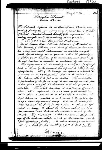
The Schedule referred to in these Letters Patent and making part of the same containing a description in the words of the said Reuben Daniels himself of his improvement in making wrought nails by machinery at one operation.
To all to whom these presents shall come.
Be it known that I Reuben Daniels of Woodstock in the County of Windsor and State of Vermont have invented a new and useful improvement in making wrought nails by machinery at one operation & that the following is a full & exact description of the construction and operation of the said machine as invented or improved by me.
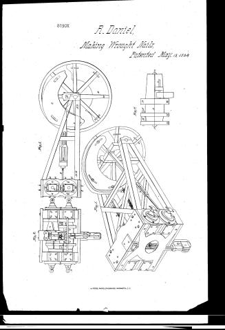
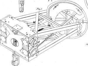
This improvement in the making or manufacturing of wrought nails is shown by the drawings here referred to & the following specification. N°1 of the drawings here referred to represents a transverse or view of the machine, prepared to receive a belt on the balance wheel to put it in motion. The construction & proportions of the frame may be considerably varied provided great strength be combined with the proper construction. The whole machine is constructed of iron & steel. N°2 represents an end view of the machine. N°3 shows a side view & at the left end are seen the boxes placed in mortices so as to move to the right or left & up & down by means of screws. C, C, in the centre of the boxes represent the places for the centres on which the cylinders are hung. W places the balance wheel made so far eccentric as to balance the eccentric motion of the crank. Thus constructed a belt will run on the periphery of the balance wheel, which in this machine does the office of driving pulley. The above drawings are calculated on a scale of two inches of a foot to the foot. The invention
Drawings
Page 3.
5/13/1834 8190x
336
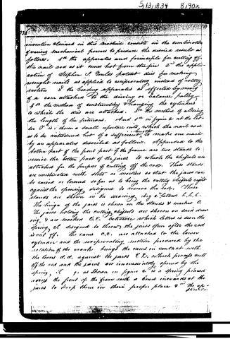
invention claimed in this machine consists in the combination of varying mechanical powers to produce the desired result as follows. 1st the apparatus and principle for cutting off the nail rod as it comes hot from the fire 2nd the application of Stephen S. Gould's patent dies for making wrought nails as applied to reciprocating instead of rotary motion 3rd the heading apparatus as effected by means of a cam attached to the driving or balance pulley—4th the method of constructing & changing the cylinders to which the dies are attached. 5th the method of altering the length of the sections. And 1st in figure 2 at the letter O is shown a small aperture into which the nail rod is to be introduced hot of a sufficient length to make one nail by an apparatus described as follows. Appended to the bottom part of the front part of the frame are two stands to receive the bottom part of the jaws to which the chisels are attached for the purpose of cutting off the rods. These stands are constructed with slots or notches so that the jaws can be raised or lowered so far as to bring the cutting chisels right against the opening designed to receive the rods. These stands are shown in the drawing Fig 2. Labeled h, h, h. The hinge of the jaws is shown on the stands & marked O. The jaws holding the cutting chisels are shown on said drawing, & are marked E, E. Between which latter is seen the spring C, designed to throw the jaws open after the rod is cut off. The cams C, C, are attached to the lower cylinder and the reciprocating motion produced by the rotation of the wheels brings the cams in contact with the levers d, d, against the jaws E, E, which forces out of the rod and the jaws are immediately opened by the spring C. g, as shown in figure 2 is a spring pinion across the front of the frame with a band inwards at the jaws to keep them in their proper place & the ap-
Page 4.
5/13/1834 8190X
337
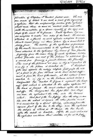
plication of Stephen S Gould’s patent axis. The axes are made of Steel & are such a part of the segment of a cylinder that the reciprocating motion of the cylinders shall cause them to come in contact with each other with the exception of a space equally of the size and shape of the nail to be formed. Each cylinder has one die adapted to make two sides of the nail. The axes are attached to a flange on each cylinder adapted to receive them & make firm in their place by a screw bolt & steady pins. The motion of the cylinders is produced by the crank communicated to the cylinders by the pitman attached to the cylinders by means of two flanges projecting from the main body of each cylinder. Between which flanges one end of the pitman is attached by a round pin forming a joint between the flanges. The ends of the pitman are seen in Fig 2 & marked b.b. & in fig 3 the pitman is marked B. 3° that part of the axis opposite the cutting shears first grips the rod at a point so far from the end as to leave metal sufficient to form the head of the nail. At this instant a cam marked C. in fig 3. on the balance wheel drives a horizontal bar marked O. figure 1. against the heading tool which is attached to the upper cylinder & the head is formed the next instant after the rod is cut off. The horizontal bar passes their two stays one near the cylinder & the other near the balance wheel. That part of the bar passing their stay on one side near the wheel is square the other portion round & is connected by a spiral spring extending from the square part of the bar to the stay. Near the cylinders the design of which is to throw the bar back after the nail is headed. After the nail is headed the cylinders continue their motion so far as to pass the
Page 5.
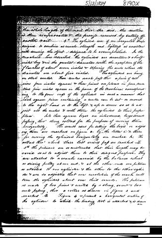
the whole length of the nail thro' the axis, the motion is then reciprocated & the process renewed by cutting off another nail. 4th. The cylinders are of an irregular shape designed to combine as much strength and lightness as consistent with securing the object designed to be accomplished. In the machine here described the cylinders are seventeen & a half inches long thro' the greatest diameter with the exception of the flanges of about seven inches & tapering the ends where the diameters are about five inches. The cylinders are hung on steel centres. These centres each pass thro' a piece of cast iron four inches square & these pieces are placed in four notches five inches square in the frame of the machine corresponding to the four ways of the cylinders in such a manner that each square piece containing a centre can be set or moved to the right hand or to the left & up or down so as to adjust all the centres & settle them the cylinders to their proper places. Into these square boxes are introduced large screws passing thro' strong collars for the purpose of moving them horizontally. The screws used for setting the boxes or adjusting them are marked on figure 2 by the letter C & those for moving the cylinders horizontally are marked h. The collars thro' which these last screws pass are marked S. 5th. The pistons are so constructed that their length may be varied so as to adjust them to their designed purpose. They are attached to a crank carried by the balance wheel or driving pulley at one end, & at the other end one piston is attached to one cylinder & the other to the other cylinder & are so adjusted that one revolution of the crank will turn the cylinders about one third rounds. The pistons are made of two pieces & united by a strong screw & two ends passing thro' a collar as shown in figure 3 and marked A. Figure 4 represents a horizontal section of the cylinders to which the bearing tool is attached & is drawn on.
Page 6.
on a scale of one third of a foot to the foot. B. represents the hammer or heading tool to be driven by the horizontal bar to form the head of the nail. This hammer or heading tool turns on a pin or pivot marked C running parallel with the longitudinal centre of the cylinder. After the head is formed a spring throws the hammer back. D represents a flange to which is attached one of the axes opposite the hammer B. — E. represents the end of the piston which gives motion to the cylinder. F. represents the pin or pivot on which the pistons between the two flanges G, H. giving motion to the cylinder. I. e. represents the centres on which the cylinder turns. Woodstock April 8th 1834.
Witnesses
Eli. L. Dunham
David Pierce
Robben Daniels
1873 wts
Exd
NYC
Published accounts: journal notice
Notice in the monthly list of patents, with remarks
Journal of the Franklin Institute, new ser., vol. 14 (1834), p. 394 · View the page
Whether the foregoing modes of procedure are perfectly new, or to what extent they are so, we leave to the experience of those in the habit of using, and keeping in order, the kind of shearing machine to which they refer. 13. For Machinery for making Wrought Nails; Reuben Daniels, Woodstock, Windsor county, Vermont, May 13.
Remarks. The claims in this machine are, "1st. The apparatus and principle of cutting off the nail rod as it comes hot from the fire. "2d. The application of Stephen J. Gold's patent dies for making wrought nails, as applied to a reciprocating, instead of a rotary, motion. "3d. The heading apparatus, as effected by means of a cam attached to the driving or balance pulley. "4th. The method of constructing and hanging the cylinders to which the dies are attached. "5th. The method of altering the length of the pitman." We do not think it necessary to compare this machine as described, with those for making wrought nails which have preceded it, and of which there is a considerable number, although, we believe, not more than one or two of them are now in use. Should this be more fortunate, and make good wrought nails with sufficient rapidity, it will afford prima facie evidence that there is enough of originality in it to entitle it to the protection of a patent.
DATAMP: illustration
Illustrations from DATAMP
DATAMP (Directory of American Tool and Machinery Patents), via the Internet Archive · Archived DATAMP page
About this record
- Patentee
- DATAMP
- Date
- the Name and Date index of patents, DATAMP, USPTO records
- Invention
- DATAMP
- Listed in
- the Name and Date index of patents, DATAMP, USPTO records, Jim Shaw's X-patent list, the Journal of the Franklin Institute, Burke's List of Patents (1847)
- Burke's 1847 Patent Office list gives the same patent.