

Drawings and documents
USPTO scan
The patent as scanned by the USPTO
-
 Page 1
-
 Page 2
-
 Page 3
-
 Page 4
-
 Page 5


U.S. Patent and Trademark Office · Google Patents
Show the transcription Hide (1,216 words)
Machine transcription (LightOnOCR) of the pages as scanned by the USPTO, most of them the handwritten copies made when the records were restored after the 1836 fire. Not checked; it can misread handwriting, so compare it with the scan.
Page 2.
United States Patent
Patent No.: X8193
John R. Morrison
Letters Patent
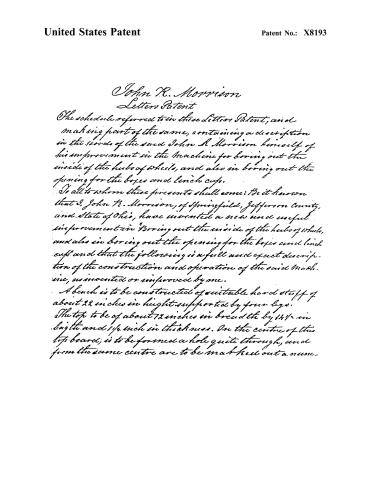
The schedule referred to in these Letters Patent, and making part of the same, containing a description in the words of the said John R. Morrison himself of his improvement in the machine for boring out the inside of the hubs of wheels, and also in boring out the opening for the boxes and lynch cups.
To all to whom these presents shall come: Be it known that I, John R. Morrison, of Springfield, Jefferson County, and State of Ohio, have invented a new and useful improvement in boring out the inside of the hubs of wheels, and also in boring out the opening for the boxes and lynch cups and that the following is a full and exact description of the construction and operation of the said machine, as invented or improved by me.
A bench is to be constructed of suitable hard stuff of about 22 inches in height supported by four legs. The top to be of about 72 inches in breadth by 14½ inches in length and 1½ inches in thickness. On the centre of this top board, is to be formed a hole quite through, and from the same centre are to be made holes out a num-
Page 3.
United States Patent
Patent No.: X8193
ber of circles of different sizes. At each end of the length of this top board, is to be attached to the underside an iron hook or projection bending downwards, for the purpose of hooking fast to an iron rod, which has its lower end flattened and perforated with holes for that purpose, these rods of which there are two, of about two feet in length, one at each end, rise perpendicularly to the cast iron frame above, and have at their top end, each a screw and nut. This cast iron circular frame, is to be of about 10 inches in diameter outside, by about 1½ inch by 1½ in thickness square. On a line with the diameter, and projecting beyond the outside of said frame, are to be formed two projections of the same thickness as the rest of the frame, opposite to each other, having at the end of each a groove for the purpose of receiving the end of the rod, and its nut above described; at the other end of the projection, in the part joining the circular frame, is another groove, in the line of the diameter of about 1½ inch in length and about 3/8 in width for the reception of screw bolts to slide in. Beneath these grooves, and to the underside of the frame is secured to each a ring of cast iron, by means of the bolt and groove just described, and by which it may be turned into presenting either side required towards the mandrel. These circles are to be formed into concave circles of different circumferences to each. About halfway between these projections is to rise from the frame in an oblique line, tending to the centre, an arm of the same metal of about 3 inches in height, having the top flattened, in a plane parallel to that of the frame presenting a surface of about 2 inches in diameter, with a hole through the centre, immediately over this hole, and on this flat surface rests a die frame, consisting of a long flat piece of metal about 5 inches in length, and 2½
Page 4.
United States Patent
Patent No.: X8193
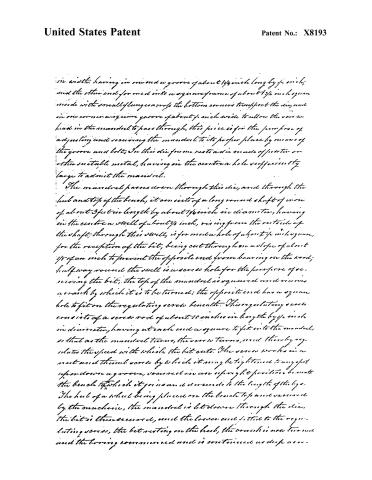
in width, having in one end a groove of about 1/4 inch long by 1/4 inch; and the other end formed into a square frame of about 1 3/4 inch square inside with small flanges across the bottom corners to support the die, and in one corner a square groove of about 1/4 inch wide to allow the screw head in the mandrel to pass through, this piece is for the purpose of adjusting and securing the mandrel to its proper place by means of the groove and bolt. In this die frame rests a die made of steel or other suitable metal, having in the centre a hole sufficiently large to admit the mandrel.
The mandrel passes down through this die, and through the hub and top of the bench, it consists of a long round shaft of iron of about 3 feet in length by about 1/4 inch in diameter, having in the centre a well of about 1/4 inch, rising from the outside of the shaft; through this well, is formed a hole of about 1/4 inch square, for the reception of the bit, being cut through on a slope of about 1/8 of an inch to prevent the opposite end from bearing on the wood; halfway round the well is a screw hole for the purpose of securing the bit. The top of the mandrel is squared and receives a crank by which it is to be turned; the opposite end has a square hole to fit on the regulating screw beneath. This regulating screw consists of a screw rod of about 10 inches in length by 1/4 inch in diameter, having at each end a square to fit into the mandrel, so that as the mandrel turns, the screw turns, and thereby regulates the speed with which the bit cuts. The screw works in a nut and thumb screw by which it may be tightened to any spot upon a groove, secured in an upright position beneath the bench to which it goes and descends to the length of the leg. The hub of a wheel being placed on the bench top and secured by the machine, the mandrel is let down through the die, the bit is then secured, and the lower end fitted to the regulating screw, the bit resting on the hub, the crank is now turned and the boring commenced and is continued as deep as re-
Page 5.
United States Patent
Patent No.: X8193
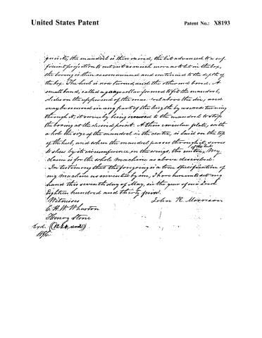
...as is its, the mandrel is then screwed, the bit advanced to a sufficient projection to cut out as much more as to let in the box, the boring is then recommenced and continued to the depth of the box. The head is now turned, until the other end bored. A small band, called a gauge collar, formed to fit the mandrel, slides on the upper end of the mandrel above the die, and may be secured in any part of the length by unscrewing turning through it; it serves by being screwed to the mandrel to stop the boring at the desired point. A thin circular plate, with a hole the size of the mandrel in the centre, is laid on the top of the head, and when the mandrel passes through it, serves to show by its circumference, on the wings, the centre. My claim is for the whole machine as above described.
In testimony that the foregoing is a true specification of my machine as invented by me, I have hereunto set my hand this seventh day of May, in the year of our Lord Eighteen hundred and thirty-four.
John R. Morrison
Witnesses
C. H. W. Wharton
Henry Stone
Exd. (1224 words)
11/96.
Published accounts: journal notice
Notice in the monthly list of patents, with remarks
Journal of the Franklin Institute, new ser., vol. 14 (1834), p. 395 · View the page
15. For a Machine for Boring out the Hubs of Wheels, and the opening for the boxes and lynch cup; John R. Morrison, Springfield, Jefferson county, Ohio, May 13.
Remarks. A bench is to be made, on the centre of which, one end of the hub to be bored is placed, concentric circles being made as guides in so doing. A cast iron frame is placed on the upper end of the hub, and is confined there by bolts which reach down to the bench, the frame being so placed as to stand with its centre exactly over that of the hub; a vertical shaft, running in suitable collars, receives at its lower end, bits, or cutters, of any desired size; this shaft is turned by a handle, or cross bar, at top. The hub may be bored half way through, and then reversed, and cutters of the proper size for the boxes, &c., may be used to enlarge the holes; the claim made is to the whole machine. The patentee is, of course, confined to the particular construction which he has described, and which we have not thought it necessary to give in detail. Such machines may be varied in numerous ways; several patents have been obtained for them under different forms, and twenty persons may yet claim to be inventors of certain special appendages, or modes of construction, which may, or may not, be improvements.
About this record
- Patentee
- DATAMP
- Date
- the Name and Date index of patents, DATAMP, USPTO records
- Invention
- DATAMP
- Listed in
- the Name and Date index of patents, DATAMP, USPTO records, Jim Shaw's X-patent list, the Journal of the Franklin Institute, Burke's List of Patents (1847)
- Burke's 1847 Patent Office list gives the same patent.