

Drawings and documents
USPTO scan
The patent as scanned by the USPTO
-
 Page 1
-
 Page 2
-
 Page 3
-
 Page 4
-
 Page 5
-
 Page 6
-
 Page 7


U.S. Patent and Trademark Office · Google Patents
Show the transcription Hide (2,453 words)
Machine transcription (LightOnOCR) of the pages as scanned by the USPTO, most of them the handwritten copies made when the records were restored after the 1836 fire. Not checked; it can misread handwriting, so compare it with the scan.
Page 2.
United States Patent
Patent No.: X8194
Herman Weiss of Meriden, Connecticut
Letters Patent
The Schedule referred to in these Letters Patent and making part of the same containing a description in the words of the said Herman Weiss himself of his improvement in the construction of clocks and time pieces.
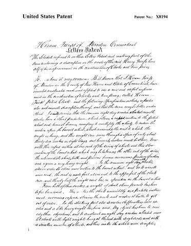
To... whom it may concern: Be it known that I Herman Weiss of Meriden in the County of New Haven and State of Connecticut, have invented constructed made and applied to use a new and useful improvement in the construction of clocks and time pieces; called Herman Weiss' Patent Clock. and the following Specification includes a particular and minute description thereof, and that the same may be better understood. I would promise that the common eight day arden wheel mantle clocks, have a short pendulum, which allows a rapid motion to the pallet wheel and hence it becomes necessary to multiply the wheels, to reduce the motion upon the barrel wheel, which unwinds the cord to which the weight is hung, and this weight can move through a space of only about thirty six inches in eight days, and hence its motion must be slow. Now with this rapid motion at one end of the series of wheels, and this slow motion of the barrel wheel which may be between the other end of the series, the intermediate wheels, teeth, and pinions become numerous, produce friction and require a very heavy weight. In the common eight day clocks, also in order to allow more motion to the barrel wheel, and so to unroll more cord, the cord is made fast at one end to the upper part of the clock case, and thereby half the weight used has no operation on the barrel wheel.
From both of these causes a weight of about eleven pounds has here so far been used. This makes the clock unwieldily as a portable instrument, increases expense, strains the work and renders it liable to get out of order. In the striking part also similar difficulties have existed and a little heavy weight has been used. My object has been to remedy these objections, and to construct an eight day arden wheel mantle clock with light weight to hang at the end with single cords and with a smaller number of wheels, and thus make the article more simple.
Page 3.
United States Patent
Patent No.: X8194
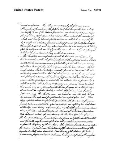
durable and portable. This I have accomplished by the following means. I have reduced the motion of the pallet wheels and through the time wheels one half by the use of the balance pendulum, constructed regulated and applied as herein set forth and described. I have reduced the number of wheels and thereby lessened friction and so am able to drive my clock by a weight not exceeding five and a half pounds, probably less hung at the end of a single cord, and have also so constructed and arranged the striking part by improvements on the fly so that it can be moved by a weight equal to that on the time side and hung in the same manner.
My invention and improvement will be best understood by describing them in connection with the principal parts of the eight day wooden wheeled mantle clocks now in use, some of which though not claimed are necessarily altered to adapt them to the improvement which are claimed. The balance pendulum which I introduce consists of a rod or bar about thirteen inches long armed with a ball of about six ounces weight at each end and falling by a curve in the bar about half an inch below the line of axis or centre of motion in which the bar vibrates, thereby producing a swinging motion. This bar is suspended on an axis at its centre about three inches long at right angles with the bar playing on a knife edge at each end, in angular sockets, or which I prefer on points passing perpendicularly into the axis near each end or inserted into the underside near the ends and projecting about one eighth of an inch. These edges or points should be of well tempered steel. The points are to play in a female centre one sixteenth of an inch deep, one eighth of an inch broad at the top, and having a flat surface, one thirtieth of an inch in diameter at the bottom also well tempered. The ends of the balance pendulum thus balanced vibrate up and down with the least possible friction. The bar and axis may be made of wood, of iron or of other suitable metal and the balls may be made of lead or other metal and ornamented in front to the fancy of the maker. This balance pendulum is supported on a stand near the bottom of the clock case containing the angular sockets above described. From the axis of the balance pendulum a wire rises perpendicular about three inches long and passing through a
Page 4.
United States Patent
Patent No.: X8194
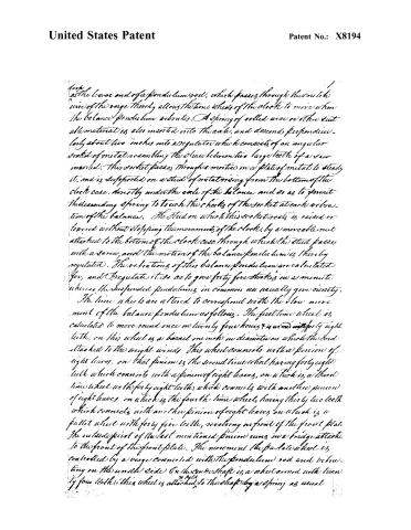
at the lower end of a pendulum rod, which passes through the small wheel in the verge thereby allows the time wheels of the clock to move when the balance pendulum vibrates. A spring of coiled wire or other suit material is also inserted into the axle, and descends correspondingly about two inches into a regulator which consists of an angular socket of metal resembling the space between two large teeth of a saw inserted. This socket passes through a mortise in a plate of metal to steady it, and is supported on a stud of metal rising from the bottom of the clock case, directly under the axle of the balance and so as to permit the descending spring to touch the cheeks of the socket at each vibration of the balance. The stud on which this socket rests is raised or lowered without stopping the movement of the clock, by a moveable nut attached to the bottom of the clock case through which the stud passes with a screw, and the motion of the balance pendulum is thereby regulated. The vibrations of this balance pendulum are calculated for, and regulate it so as to give forty five strokes in a minute, whereas the suspended pendulums in common use usually give ninety.
The time wheels are altered to correspond with the slow movement of the balance pendulum as follows. The first time wheel is calculated to move round once in twenty four hours & is wound with forty eight teeth; on this wheel is a barrel one inch in diameter on which the cord attached to the weight winds. This wheel connects with a pinion of eight leaves, on that pinion is the second time wheel having forty eight teeth which connects with a pinion of eight leaves, on which is a third time wheel with forty eight teeth, which connects with another pinion of eight leaves on which is the fourth time wheel, having thirty two teeth which connects with another pinion of eight leaves on which is a pallet wheel with forty five teeth, revolving in front of the front plate. The outside point of the last mentioned pinion runs in a bridge attached to the front of the front plate. The movement the pallet wheel is controlled by a verge connected with the pendulum rod and vibrating on the under side. On the conno shaft is a wheel armed with twenty four teeth; this wheel is attached to the shaft by a spring as usual
Page 5.
United States Patent
Patent No.: X8194
and connects with a pinion of sixteen leaves on the second time pinion shaft, and thereby moves the centre shaft. On the back end of the centre shaft is a pinion of nine leaves, connected with a wheel of thirty six. In this wheel is a pinion of twelve leaves, connected with another wheel of thirty six teeth and in that wheel is the hour hand socket through which the centre shaft passes, which carries the minute hands. These wheels and pinions, and other parts not described are supposed to be of the ordinary size and dimensions commonly used in mantle piece clocks, but may be proportionally enlarged or decreased. The number of teeth and leaves are calculated for the motion of a pendulum beating forty five strokes in a minute and is the calculation which I prefer, but the same result may on due calculation be produced by varying the number of teeth in the different wheels and pinions excepting the pointer wheels & centre shaft. They may also be varied by proper calculation to suit the vibration of any pendulum, longer or shorter or moving slower or faster. With these alterations in the time wheels my improved clock will move with much less friction, and with the weights on a single cord, not exceeding and probably less than half the required weight on a double cord now used in eight day clocks. The improved balance pendulum as above described is also less liable to the effects of heat and cold than the suspended pendulum in common use; in as much as the expansion and contraction of this pendulum is counteracted by the corresponding contraction or expansion of the regulator.
My improvement in the striking part is as follows. The first strike wheel so called is made to revolve once in twenty four hours, and is armed with forty eight teeth. In it is a barrel one inch in diameter on which the cord attached to the weight winds. This wheel connects with a pinion of eight leaves, on that pinion is a second wheel which revolves six times in twenty four hours. On the face of this wheel are twenty six comers placed at equal distances which raise the hammer that strikes the bell. Playing into these comers is a verge the shaft of which is directly over the shafts of the first and second strike wheels. This verge moves in a manner similar to that on the time side, and controls the
Page 6.
United States Patent
Patent No.: X8194
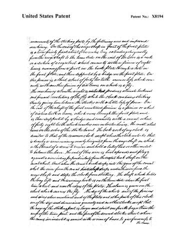
movements of the striking parts by the following new and improved machinery. On the end of this verge shaft, in front of the front plate is a lever firmly fixed about five inches long extending diagonally from the verge shaft to the time side on the end of the lever is a rack or section of a cogwheel which connects with a pinion of eight leaves, running from a pivot in the back plate through a hole in the front plate, and there supported by a bridge on the front plate. On this pinion is a third wheel of forty two teeth more or less, which connects with another pinion of six leaves, on which is a fly.
The machinery when the weight is unloosed produces alternate backward and forward revolutions of the fly while the clock continues striking thereby giving time between the strokes with a little loss of power. On the end of the shaft of the first mentioned pinion is a pinion or wheel of six teeth or leaves, which runs through the front plate and is thus supported by a bridge and connects with a count wheel of forty eight teeth which revolves once in twelve hours. The count wheel turns on the axis of the strike barrel. The lock work of my clock is similar to that of the common clock except when the clock unlocks, that is done by a wire running nearly horizontal from the verge shaft on which is the thread of a screw to receive and hold a ball of lead or other metal to balance the lever. The end of this wire is bent upwards and plays against a wire riding perpendicularly from the count hook shaft on the count wheel. And when the count hook drops into the gain of the count wheel the wire from the count hook shaft drops under this wire from the verge shaft and stops the clock from striking. The shaft which holds the long lift and the warning hook is on the time side above the first time wheel and near the edges of the plates. The alarm is given on the wheel which carries the fly. The size of the wheels and of the pinions and wires above mentioned and of the plates and other parts of this clock are of the size and dimensions generally used in other clocks, except that the verge of the striking part is large and about one fourth longer than the verge of the time part, and the face of the second strike wheel where the cams are inserted is armed with a rim of brass to give firmness to the cams.
Page 7.
United States Patent
Patent No.: X8194
to the cams. The several parts herein before described will be seen more in detail by reference to the model and drawings accompanying this specification.
I do not claim a balance pendulum as such to being my invention; but I do claim as my invention and improvement, the successful and advantageous application of the slow motion of the balance pendulum to the movement of any portable or wall clock or time piece.
I do also claim as my original invention the regulator, as above specified whereby the motion of the pendulum is controlled by a spring and its expansion and contraction counteracted. I also claim as my invention and improvement, the construction of the striking part as above specified, whereby the fly is made to revolve backward and forward by means of the lever on the verge shaft and its connection with the fly as above specified, thereby checking and controlling the hammer more effectively and with less loss of power than can be done by a continued revolution of the fly as in common use and requiring less weight and less space for its descent. The other parts of a clock mentioned and described in the foregoing specification are introduced for illustration, and I do not claim any of them except the alterations necessarily made to adapt them to the improvement herein particularly specified as claimed, and for the improvements thus specified I solicit Letters Patent to secure the benefits according to Law.
In testimony that the foregoing is a true and full specification of my improvements, I subscribe thereunto this 10th day of Dec 1833.
Wm. Baldwin
Hiram Baldwin
(2590 words)
(Granted May 13, 1834)
Published accounts: journal notice
Notice in the monthly list of patents, with remarks
Journal of the Franklin Institute, new ser., vol. 14 (1834), p. 396 · View the page
17. For improvements in the Construction of Clocks and Time Pieces; Hiram Twiss, Meriden, New Haven county, Connecticut, May 13.
Remarks. The improvements described in this specification depend, in a great degree, upon the introduction of the balance pendulum, the time wheels being so altered as to answer to the slower motion of the pendulum; and the patentee says that, " with these alterations in the time wheels, my improved clock will move with much less friction, and with the weight on a single cord not exceeding, and probably less than, half the required weight on a double cord now used in eight day clocks." The balance pendulum is here again particularly described as in the foregoing patent, together with the mode of constructing the regulator; but we cannot afford the space required for their insertion. Certain improvements are also claimed in the striking part, which also we shall pass over, excepting so much of them as may be indicated by the claims, which are the following: "I do not claim a balance pendulum, as such, to be my invention; but I do claim as my invention and improvement, the successful and advantageous application of the slow motion of the balance pendulum to the movements of any portable wooden clock, or timepiece. "I do claim as my original invention, the regulator as above specified; whereby the motion of the pendulum is controlled by a spring, and its expansion and contraction counteracted. "I also claim as my invention and improvement, the construction of the striking part as above specified, whereby the fly is made to revolve backward and forward by means of the lever on the verge shaft, and its connexion with the fly as above specified; thereby checking and controlling the hammer more perfectly, and with less loss of power, than can be done by a continued revolution of the fly as in common use, and so requiring less weight, and less space for the descent." We do not perceive the necessity for two patents for the foregoing improvements, as the whole appertains to the same instrument, a time piece, and the first, the balance pendulum, is specially mentioned as applied in the second patent.
About this record
- Patentee
- DATAMP
- Date
- the Name and Date index of patents, DATAMP, USPTO records
- Invention
- DATAMP
- Listed in
- the Name and Date index of patents, DATAMP, USPTO records, Jim Shaw's X-patent list, the Journal of the Franklin Institute, Burke's List of Patents (1847)
- Burke's 1847 Patent Office list gives the same patent.