

Drawings and documents
USPTO scan
The patent as scanned by the USPTO
-
 Page 1
-
 Page 2
-
 Page 3
-
 Page 4


U.S. Patent and Trademark Office · Google Patents
Show the transcription Hide (984 words)
Machine transcription (LightOnOCR) of the pages as scanned by the USPTO, most of them the handwritten copies made when the records were restored after the 1836 fire. Not checked; it can misread handwriting, so compare it with the scan.
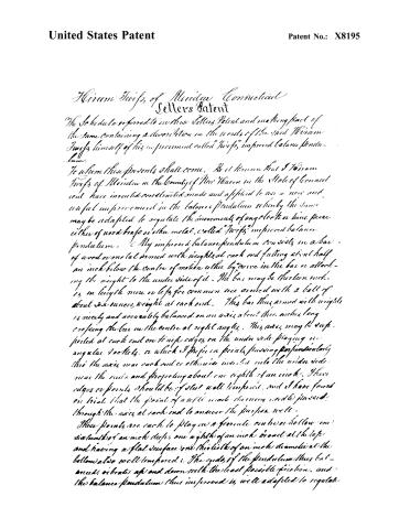
Page 2.
United States Patent
Patent No.: X8195
Hiram Swift of Meriden Connecticut
Letters Patent
The Schedule referred to in these Letters Patent and making part of the same containing a description in the words of the said Hiram Swift himself of his improvement called "Swift's improved balance pendulum."
To whom these presents shall come. Be it known that I Hiram Swift of Meriden in the County of New Haven in the State of Connecticut have invented constructed, made and applied to use a new and useful improvement in the balance pendulum whereby the same may be adapted to regulate the movements of any clock or time piece either of wood brass or other metal, called "Swift's improved balance pendulum." My improved balance pendulum consists in a bar of wood or metal armed with weights at each end falling about half an inch below the centre of motion either by a curve in the bar or attaching the weight to the under side of it. The bar may be thirteen inches in length more or less for common use armed with a ball of about six ounces weight at each end. This bar thus armed with weights is nicely and accurately balanced on an axis about three inches long crossing the bar in the centre at right angles. This axis may be supported at each end on knife edges on the under side playing in angular sockets, or which I prefer in points passing perpendicularly thru the axis near each end or otherwise inserted into the under side near the ends and projecting about one eighth of an inch. These edges or points should be of steel well tempered, and I have found on trial that the point of a well made turning needle passed through the axis at each end to answer the purpose well.
These points are each to play in a female cut in a hollow one sixteenth of an inch deep, one eighth of an inch broad at the top and having a flat surface one thirty-sixth of an inch diameter at the bottom also well tempered. The ends of the pendulum thus balanced, vibrate up and down with the least possible friction, and the balance pendulum thus improved is well adapted to regulate
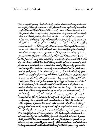
Page 3.
United States Patent
Patent No.: X8195
The movements of any kind of clock or time pieces and may be connected in the following manner. This pendulum is supported on a stand or shelf near the bottom of the clock case. From the axis of the pendulum a wire rises perpendicularly about three inches long and passing through a loop at the lower end of a pendulum rod, which passes through the center wire of the verge, thereby allowing the time wheels of the clock to move when the balance pendulum vibrates. A spring of rolled wire or other suitable material is also inserted into the axle and descends perpendicularly about two inches into a regulator. The regulator consists of an angular socket of metal resembling the space between two large teeth of a saw inserted, about one sixteenth of an inch thick. This socket opens on the top about three fourths of an inch and is supported on a stud of metal about two inches long, rising from the bottom of the clock case directly under the axle of the balance and so as to permit the descending spring to touch the cheeks of the socket at each vibration of the balance. The lower end of the stud is a screw passing through a nut resting on the bottom of the clock case and prevented from rising by a loop or bridge made fast to the bottom of the case through which the stud also passes, so that by turning the nut fast to its place by the bridge, the stud will rise or fall and carry with it up or down the regulator which is guided by a mortise through which it moves in a plate of metal attached to the shelf where it supports the pendulum. Raising or lowering the regulator will accelerate or retard the vibrations. This improved pendulum will also regulate itself as to the effects of heat and cold, inasmuch as the expansion and contraction of this pendulum is counteracted by the corresponding contraction or expansion of the regulator. The balance pendulum above described is calculated for and regulates it so as to give forty-five strokes in a minute, whereas the suspended pendulum in common use usually gives ninety. This invention will lead to useful improvements in the construction of all time pieces regulated
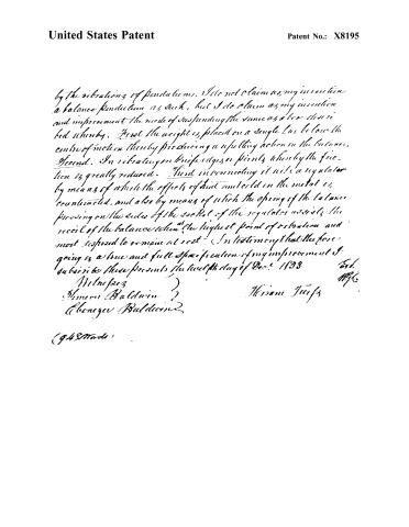
Page 4.
United States Patent
Patent No.: X8195
by the vibrations of pendulums. I do not claim as my invention a balance pendulum as such, but I do claim as my invention and improvement the mode of suspending the same as a lever described whereby. First the weight is placed on a single bar below the centre of motion thereby producing a reselling action in the balance. Second. In vibrating on knife edges or points whereby the friction is greatly reduced. Third in connecting it with a regulator by means of which the effects of heat and cold in the metal is counteracted, and also by means of which the spring of the balance pressing on the sides of the socket of the regulator assists the recoil of the balance when at the highest point of vibration and most disposed to remain at rest. In testimony that the foregoing is a true and full specification of my improvement I subscribe these presents the twelfth day of Dec. 1833
Wm. Baldwin
Cheney Baldwin
Hiram Jurgs
(948 words)
Published accounts: journal notice
Notice in the monthly list of patents, with remarks
Journal of the Franklin Institute, new ser., vol. 14 (1834), p. 396 · View the page
16. For a Balance Pendulum; Hiram Twiss, Meriden, New Haven county, Connecticut, May 13.
Remarks. After describing the pendulum, the patentee says, "I do not claim as my invention, a balance pendulum, as such; but I claim as my invention and improvement, the mode of suspending the same as above described; whereby, first, the weight is placed on a single bar below the centre of motion, thereby producing a repelling action in the balance. Second, in vibrating on knife edges, or points, whereby the friction is greatly reduced. Third, in constructing it with a regulator, by means of which, the effects of heat and cold on the metal is counteracted, and also by means of which, the spring of the balance pressing on the sides of the sockets of the regulator, assists the recoil of the balance when at the highest point of vibration, and most disposed to remain at rest." "The balance pendulum above described is calculated for, and I regulate it so as to give, forty-five strokes in a minute; whereas the suspended pendulums in common use usually give ninety. This invention will lead to useful improvements in the construction of all time pieces regulated by the vibrations of a pendulum."
About this record
- Patentee
- DATAMP
- Date
- the Name and Date index of patents, DATAMP, USPTO records
- Invention
- DATAMP
- Listed in
- the Name and Date index of patents, DATAMP, USPTO records, Jim Shaw's X-patent list, the Journal of the Franklin Institute, Burke's List of Patents (1847)
- Burke's 1847 Patent Office list gives the same patent.