

Drawings and documents
National Archives restored drawings: drawing
John Haight's Patent Drawing for a Loom for Weaving Carpets and Other Figured Cloths


National Archives, Restored Patent Drawings (Record Group 241) · Full-size scan at the National Archives · Catalog record
Show the text on the drawing Hide (55 words)
Words on the drawing as machine-read by the National Archives; not checked. Useful mainly for searching.
Sheet 1. 139 -WEAVING / Looms, Looms / CLASSIFICATION / 8208 X / DIVISION. / John Haight's / Loom for wearing carpots & other figured cloths. / Patented May 17. 1834. / LE
Sheet 2. (39. WEAVING. / Looms, Looms: / classinication / 8208-x / DIVISION.
Sheet 3. DD / FR / to / alo / DIVISION. / X socs / CLASSI TICATION / swoot / 681
USPTO scan
The patent as scanned by the USPTO
-
 Page 1
-
 Page 2
-
 Page 3
-
 Page 4
-
 Page 5
-
 Page 6
-
 Page 7
-
 Page 8
-
 Page 9
-
 Page 10
-
 Page 11
-
 Page 12
-
 Page 13
-
 Page 14
-
 Page 15
-
 Page 16
-
 Page 17


U.S. Patent and Trademark Office · Google Patents
Show the transcription Hide (5,360 words)
Machine transcription (LightOnOCR) of the pages as scanned by the USPTO, most of them the handwritten copies made when the records were restored after the 1836 fire. Not checked; it can misread handwriting, so compare it with the scan.
Page 1.
8208X
J. Haight.
Loom.
Patented May 17, 1834.
Sheet 1-3 Sheets.
Page 2.
8208X
Sheet 2-3 Sheets.
J. Haight.
Loom
Patented May 7, 1834.
Page 3.
8208X
J. Haight Loom.
Patented May 17, 1834.
Sheet 3 - 3 Sheets.
H. PETERS, PHOTO-LITHOGRAPHER, WASHINGTON, D. C.
Page 4.
5/17/1834 8208 x
John Haight May 17, 1834
Letters Patent
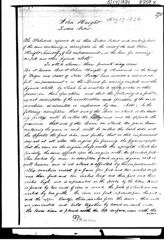
The Schedule referred to in these Letters Patent and making part of the same containing a description in the words of the said John Haight himself of his improvement in the loom for weaving carpets and other figured cloths.
To all to whom these presents may come
Be it known that J. John Haight of Haverhill in the County of Bergen and State of New Jersey have invented a new and useful improvement in the Looms for weaving carpets and other figured cloths, by which he is enabled to apply water or other power in their operation, and that the following is a full and exact description of the construction and operation of the said machine, as invented or improved by me. Note: In the following description that end of the loom on which is the driving pulley will be called the pulley end and the opposite the gear end, that side of the loom on which the yarn beam containing the yarn or weft will be called the back side and the opposite the front side, and further that as this improvement does not at all alter the engine for forming the figure except that the cam on the engine shaft works the uprights which has precisely the same effect upon the engine with the operators foot when worked by men, no description of said engine is given, as it is well known and is not altered or affected by this improvement.
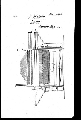
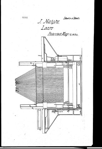
This machine consists of a frame four feet and two inches deep and three feet and ten inches long and three feet and three inches high and is represented on the plate by the letter A and is formed by two ends of iron or wood, the parts of which are connected by two girdles, the lower one foot upwards from the feet, and the upper twenty-three inches from the lower, these ends are connected and held together by beams on each end, the lower beam is placed with the top surface even with the under
Page 5.
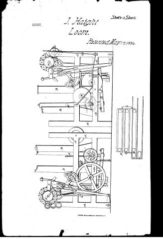
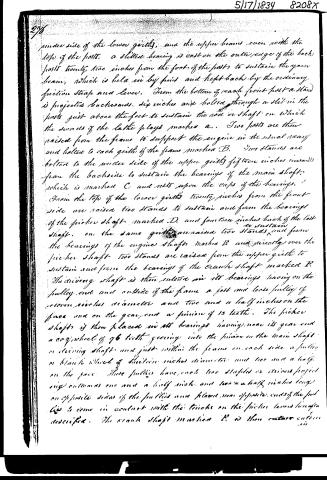
under side of the lower girths, and the upper beams even with the top of the posts. A slitted bearing is cast on the outer edge of the back posts twenty-two inches from the foot of the posts to sustain the yarn beam, which is held in by pins and kept back by the ordinary friction strap and lever. From the bottom of each front post a stand is projected backwards, six inches and bolted through a slot in the posts just above the feet to sustain the rod or shaft on which the swivels of the lathe plays marked a. Two posts are then raised from the frame to support the engine in the usual way and bolted to each girth of the frame marked B. Two stands are bolted to the under side of the upper girths fifteen inches inward from the backside to sustain the bearings of the main shaft, which is marked C and rests upon the caps of the bearings. From the top of the lower girths twenty inches from the front side are raised two stands to sustain and form the bearings of the picker shaft marked D, and fourteen inches back of the lathe shaft, on the same girths are raised two stands to sustain and form the bearings of the engine shaft marked E and directly over the picker shaft two stands are raised from the upper girth to sustain and form the bearings of the crank shaft marked F. The driving shaft is then entered in its bearings leaving on the pulley end and outside of the frame a fast and loose pulley of sixteen inches diameter and two and a half inches on the face and on the gear end a pinion of 13 teeth. The picker shaft is then placed in its bearings having near its gear end a cog wheel of 76 teeth gearing into the pinion on the main shaft or driving shaft and just within the frame on each side a pulley or blank wheel of thirteen inches diameter and two and a half on the face. These pulleys have each two staples or drivers projecting outwards one and a half inch and two and a half inches long on opposite sides of the pulleys and placed near opposite ends of the pulleys to come in contact with the tacks on the picker levers hereinafter described. The crank shaft marked E is then entered in
Page 6.
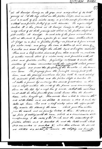
and its bearings having on its gear end a cog wheel of 24 teeth gearing in 1 to the cog wheel on the picker shaft; and on each end a crank of 4 1/2 inches radius, or 9 inches square furnished with a stud and friction pulley of 14 inches diameter. The engine shaft marked B is then placed in its bearings having on the gear end a cog wheel of 48 teeth gearing into wheel on the picker shaft and just within its bearings. On each side of the frame a crank stud slot in the ends to form a guide for an oval cam, within which it plays on a stud or friction pulley so placed as to form a crank of 3 inches radius, and giving the cam a motion up and down of 6 inches and serves to shift the shuttle boxes as hereafter described. Four and a half inches, inwards from these cranks on each side is another crank stud of 5 inches radius and furnished with its stud and friction roller, projecting outwards to raise the section of a cam, connected with the upright which governs the engine and serves the purpose of the handles in the common loom. The foregoing form the principle moving parts of the loom, and the gearing mentioned has five teeth to each inch of the diameter of the wheels and the picker shaft is marked D.
A lathe is formed by entering two swords of cast iron on their rods or shaft within the ends of the frame and connecting them on the top by a cross bar of wood, so that the race bar on it will be three-fourths of an inch lower than the breast beam when brought up. These swords have a hole to receive the rod at the bottom and are slotted to receive a stud to work the lathe rope lever. Two and a half inches above the upper girth they receive the stands of the cam, which gives them motion from the cranks and are firmly bolted to them. This stand is of one piece of casting with the cam, which is a semicircular slot corresponding to the radius of the crank and the diameter of its friction roller and is marked E, and the lathe with which it is connected is marked C; above these stands the swords are slotted 1/4 inch upwards to receive the shifting rod hereafter mentioned.
Page 7.
278.
mentioned the slay or reed frame is then placed on the back side of the frame bar of the lathe, with its end pieces projecting upwards eight inches to receive the top piece which is mortised for them and the slay is received and held firm by grooves in the bottom and top pieces in the usual way of frame looms, and the upper ends of the swords are cast with flanges to receive the warp bar and the bottom piece of the slay frame through which they are firmly bolted at each end. This formed this part constitutes the moving lathe, having an irregular but uniform motion carrying the slay to and from the work.
Six swords are then placed upon the part of the lathe and just out side of the frame and ride to the same height with the swords before mentioned and serves to sustain the shuttle box at each end of the lathe. Six inches up from the rod, there swords is a socket guide and nineteen inches above this it receives another for the rod which turns the shuttle wheel hereafter mentioned, and six inches below the last mentioned socket the sword receives a stud for a fence which shifts the forks of the rod before mentioned to and from each side of the wheel which it moves together with this stud and between it and the sword a small stand is raised and projected forwards and outwards to sustain the bottom of a spiral spring and receive a friction wire inches above this another stand is projected upwards and forwards from the sword to hold the upper guide of the rod through which it passes and is formed into a steady beam or fitting the sides of the shuttle wheel, a spiral spring is placed between the guides and the rod is passed down through the guides and the spring and is held by a pin through the rod resting upon the top of the spring so that the power of the spring is employed to keep the shuttle box in place when it had been moved as hereafter described. Above this last mentioned stand the
Page 8.
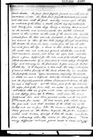
sword divides. The front part projects forwards one inch and upwards seven inches. The back part projects backwards five inches and rises even with the front; and they receive upon the top on each side of the loom, a double shuttle box six inches wide and twenty-five inches long having a dividing board in each in the middle, and accommodates two shuttles. A small sword is then entered on the ends of the sword rods, six inches outwards from the last and rise parallel to them two feet and are secured to them by two bolts passing through slits between the swords, the lower one seven inches from the rod, the other one inch from the top. A brace is then bolted to an ear on the under side and outer end of each shuttle box and to the last mentioned sword just below the upper bolt, and thus forms a firm support for the outer ends of the shuttle boxes which are connected by a firm piece of wood passing back of the slay and cut away on the front side to give room for the front shuttle box to be brought in a line with the slay which piece of wood is bolted firmly to the back shuttle box on each side the part of the sword before mentioned projecting backwards, is slitted one and a half inch below the division perpendicularly and the projecting parts also slitted perpendicularly near the top one and a half inch, and the lower part of the top slit and the upper part of the lower slit, are united by an angular stir, all which slits are of an inch wide and so formed that a rod passing from top to bottom, will move the sword backwards two and three quarters inches and the rod will move forwards four inches. The back division of the shuttle box on the gear end and both divisions of the shuttle box on the pulley end, are in form like the common shuttle box if you have never seen in the bottom to guide the picker and furnished with friction springs to hold the shuttle and picker from rebounding when they arrive in their places. But as many different coloured yarns must be woven into one piece
Page 9.
5|17|1834 8208X
280.
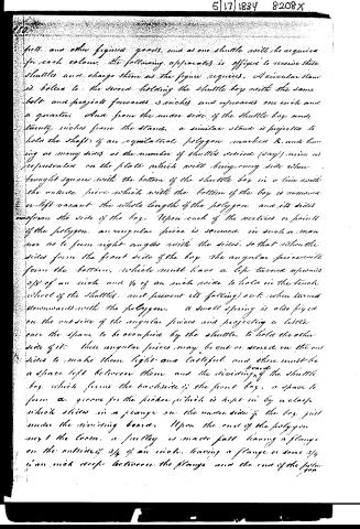
pits, and other figured goods, and as one shuttle will be required for each colour, the following apparatus is offered to receive these shuttles and charge them as the figure requires. A circular stand is bolted to the sword, holding the shuttle box with the same bolt and projects forwards 3 inches and upwards one inch and a quarter. And from the under side of the shuttle box, and twenty inches from the stand, a similar stand is projected to hold the shaft of an equilateral polygon marked K, and having as many sides as the number of shuttles desired (say) nine as represented on the plate which will bring every side when brought square with the bottom of the shuttle box in a line with the outside piece which with the bottom of the box is removed or left vacant the whole length of the polygon and its sides conform the side of the box. Upon each of the vertices or points of the polygon, an angular piece is screwed in such a manner as to form right angles with the sides, so that when the sides form the front side of the box, the angular pieces will form the bottom, which must have a lip turned upwards 3/8 of an inch and 1/4 of an inch wide to hold in the tuck wheel of the shuttles, and prevent its falling out when turned downwards with the polygon. A small spring is also fixed on the outside of the angular pieces and projecting a little over the space to be occupied by the shuttle, to hold the other side of it. These angular pieces may be cut or screwed on the outside to make them light and tasteful, and there must be a space left between them and the dividing board of the shuttle box which forms the backside of the front box, a space to form a groove for the picker which is kept in by a clamp which slides in a flange on the under side of the box just under the dividing board. Upon the end of the polygon next the loom, a pulley is made fast having a flange on the outside 3/4 of an inch, having a flange or some 3/4 of an inch deep between the flange and the end of the polygon.
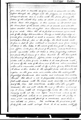
Page 10.
gon, nine pins or tunnels 1/4 of an inch in diameter are then passed through the flange into the polygon, in a circle and at equal spaces, and in a line with the pieces forming the bottom of the shuttle box when its shuttle is in action. The rod which turns this polygon, is then entered in its socket near the lower part of the sword, where it is round, and into the upper socket where it is flat and has room to move sideways 1/2 of an inch. Above this it is forked and comes upon each side of the pulley last mentioned, having a catch projecting inwards from each fork in such a manner that when the front catches in holes of pins in the pulley, the back catches will be free, or pass its pin without a contact, and (vice versa) a stand is then bolted to the inside of the lower guide on the gear end fifteen inches from the front of the frame, and extends downwards 3 1/2 inches where it takes a stud projecting outwards and forms the fulcrum of a lever marked L. This lever extends backwards of the fulcrum fifteen inches and forwards of it five inches when a piece of iron is bolted to it, and forwards until it comes by the side of the lower end of the rod above mentioned where it is connected with it by a piece of iron bolted to each. A stand is then bolted to the upright piece which works the engine, on the gear side nine inches above the upper guide, projecting backwards two inches and outwards two inches. Through this stand a rod is projected downwards and made fast with screws with the lower end directly over the back end of the lever last mentioned, so that when the upright descends, this rod will strike the end of the lever and carry it down with it, consequently raises the other end and carrying with it the rod before mentioned which by the catch of the fork which is in gear with it winds the pulley to move just one revolution part of a revolution and bring a new shuttle in place. The catches on the front side of the forks of the rods will always tend to be in action with the pins.
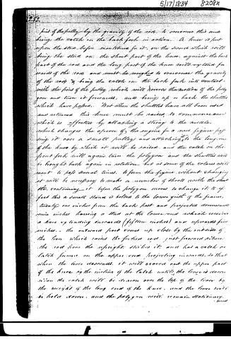
Page 11.
282.
find of the pulley by the gravity of the rod, to overcome this and bring the catch on the back fork in action. A fence is put upon the stud before mentioned for it, on the sword which will bring the stud on the short part of the fence, against the back part of the rod and the long part of the fence will extend forwards of the rod and must be weighed to overcome the gravity of the rod & bring the catch on the back fork into contact with the find of the pulley which will reverse the motion of the polygon and turn it forwards, and bring up or back the shuttles which have passed. But when the shuttles have all been used and returned this fence must be raised to commence anew which is effected by attaching a string to the needle, which changes the apron of the engine for a new figure passing it over a small pulley and attaching it to the long arm of the fence by which it will be raised, and the catch on the front fork will again turn the polygon and the shuttles will be brought back again in rotation, but as some of the colors will want to pass several times to form the figure without changing it will be necessary to make a number of sheets with the shuttle, containing it before the polygon moves to change it: to effect this a small stone is bolted to the lower girth of the frame, twenty one inches from the back post and projected downwards nine inches having a stud at the lower end which receives a knee extending inwards (fifteen inches) and upwards five inches. The outward part comes up close by the outside of the lever which raises the foreseen rod, just forward where the rod from the upright strikes it and has a catch or latch former on the upper end projecting inwards, so that when the lever descends, it will cross out the upper part of the knee by the incline of the latch until the lever is down when the catch will be drawn over the top of the knee by the weight of the long end of the knee, and the fence will be held down, and the polygon will remain stationary.
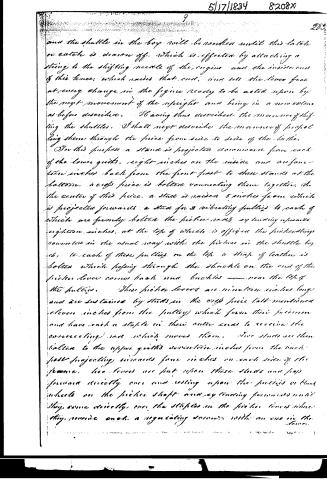
Page 12.
and the shuttle in the box will be worked until this latch or catch is drawn off, which is effected by attaching a string to the shifting needle of the engine and the inside end of this knee, which raises that end, and sets the lever free at every change in the figure ready to be acted upon by the next movement of the upright and bring in a new column as before described. Having thus described the manner of shifting the shuttles, I shall next describe the manner of propelling them through the piece from side to side of the loom.
For this purpose a stand is projected downwards from each of the lower guides, eight inches on the inside and one-fourteen inches back from the front post to these stands at the bottom, a cross piece is bolted connecting them together. In the center of this piece, a stud is raised 5 inches from which is projected forwards a stud for 2 vibrating pulleys to each of which are firmly bolted the picker rods extending upwards eighteen inches, at the top of which is affixed the pickering connection in the usual way with the pickers in the shuttle box, to each of these pulleys on the top a strap of leather is bolted which passing through the shackle on the end of the picker lever comes back and buckles near the top of the pulleys. These picker levers are nineteen inches long and are sustained by studs in the cross piece last mentioned eleven inches from the pulley which form their fulcrum and have each a staple in their outer ends to receive the connecting rod which moves them. Two studs are then bolted to the upper guides seventeen inches from the back post projecting inwards four inches on each side of the frame, two levers are put upon these studs and pass forward directly over and resting upon the pulleys or blank wheels on the picker shaft and extending forwards until they come directly over the staples in the picker levers where they provide each a negotiating surface with an eye in the lever.
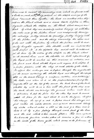
Page 13.
lower end to receive the connecting rods, which are formed with a hook on each end, which being entered in the staple and eye of the levers connects them together. The levers are mortised where they rest on the blank wheels and a scored track is fitted in them against which the staples on the blank wheel come in contact by which they are suddenly raised bringing up with them the outer ends of the picker levers and consequently turning the vibrating pulley towards the operating pulley, bringing with it the picker rod and the string connecting the upper end of the rod with the picker, by which the picker will be suddenly brought against the shuttle with an impulse that will propel it to the opposite bay, and it will be returned in its time by the action of the staple on the blank wheel on its match-lever and the shuttles in both apartments of the bays will be worked in this manner in rotation, and the front and back shuttle boxes will require to be shifted to a proper position with the stay at each stroke of the lathe.
To effect this a change rod is passed through the angular slot in the swords sustaining the shuttle boxes and through the upright slots in the swords having a uniform motion, and sustaining the lathe, and when it is in the perpendicular part of the angular slot at the top of the sword, the back board of the back shuttle box will be in a line with the front of the stay and the back shuttle containing the ground colour will be in a situation to pass the piece but the other box must be moved into its place for the next sheet to make the figure. To effect this change the eye of a rod is passed round this change rod just within the inside swords, and extends downwards twenty-five inches where it enters a slot in the end of a lever and is held to it by a pin passing through each part of the lever and the rod which is here made flat. This lever extends backwards fourteen inches, where it receives a pin in a stand on the inside of the lower guide, which serves as its fulcrum.
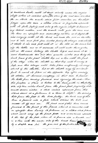
Page 14.
is continued back until it comes directly under the engine shaft where it receives upon the slam of the oval cam marked M. on which the crank stud first described, on the shaft plays. Upon this cam a slotted stand is projected upwards with its forks passing each side of the engine shaft to prevent any lateral motion, and the crank will give the cam and the lever an upright and descending motion as it passes its side carrying with it the lever and cause the rod on the other end to rise and fall four inches forcing the change rods which it clasps to rise and fall with it in the slots in the second holding the latter and as it descends, it will enter the angular slot in the second holding the shuttle boxes and cause it to move backwards two and three quarter inches and bring the back board of the front shuttle box in a line with the front of the slay. When the shuttle in that box will be ready to pass, and this change will take place uniformly at every stroke of the shuttle, but as the shuttle may by accident fail to reach its place in the opposite box after receiving its stroke, it becomes necessary, in that case to prevent the latter from coming forward and injuring the web. For this purpose a stand is bolted to the lower guide on the pulley side sixteen inches back from the front post projecting outwards seven inches, a stud raised upwards from this stand serves as a fulcrum to a lever to shift the driving belt from the fast to the loose pulley. The back end of this lever is formed into a fork which straddles the belt and moves it off and on. The front end of this lever comes forward to the front of the frame where it is connected with an upright lever having its fulcrum in a slotted stud placed about nine away up the front post, and is continued upwards to the top of the post where it is formed into a handle, and in a line with the center side of the breast beam, and receives by a staple and pin the gear end of the front stud.
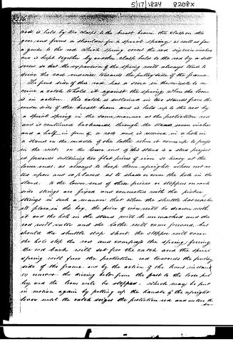
Page 15.
rod is held by two clasps to the breast beam. The clasp on the gear end forms a shoulder for a spiral spring, as well as for a guide to the rod. Which spring covers the rod sixteen inches and is kept together by another clasp held to the rod by a set screw so that the expansion of the spring will always tend to drive the rod endwise towards the pulley side of the frame.
The front side of this rod has a score in the middle to receive a catch to hold it against the spring when the loom is in action. This catch is sustained in two stands from the under side of the breast beam and is held up to the rod by a spiral spring in the same manner as the protection rod and is continued backwards, through the stands seven inches and a half in form of a rod and is received in a hole in a stand on the middle of the lathe when it comes up to props in the wrist. On the lower end of this stand is a stud projected forwards sustaining two flat pieces of iron so heavy at the lower ends, as always to keep them upright, when not acted upon and so placed as to shade or cover the hole in the stand. To the lower end of these pieces or stoppers on each side strings are fixed and connected with the picker strings in such a manner that when the shuttle has reached its place in the box, the piece of iron will be drawn with it and the hole in the stand will be unmarked and the rod will enter and the lathe will come forward, but should the shuttle stop short, the stopper will cover the hole stop the rod and compress the spring forcing the rod back will set free the catch and the spiral spring will force the protection rod towards the pulley side of the frame and by the action of the levers instantly remove the driving belt from the post to the loose pulley and the loom will be stopped, which may be put in motion again by pulling up the handle of the upright lever until the catch seizes the protection rod and arrests the
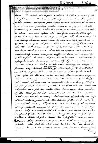
Page 16.
5|17|1834 8208X
13 28
severe. To work the engine a stand is bolted on each of the upright pieces which move the engine marked N—right inches above the upper girdles and turned inwards three inches and downwards fourteen inches when it is formed into the section of a circle with the ends extended in a line with its chord, and rests upon the hub of the crank shaft, before described as inside on the engine shaft with its centre reversed and having the same radii with the cranks which are placed on opposite sides of the shaft so that when one upright is raised the other will remain quiet and these cams or sections of circles must be so formed that the one upright will rise and consequently, down and give sufficient time for the needles of the engine to recover before the other rises. These cranks and uprights will be moved alternately by the cranks, and a slotted stand is bolted to the cam, sliding the shaft to prevent any lateral motion of these uprights is all that works the engine and serves all the purposes of the man's foot upon the treadles, when working the common engine locomotive. Having now described the manner of making the works it remains to describe the method of taking it away as it is made, for which purpose the common wheel and pinion with their lever and legs worked by the studs for this before mentioned on the second of the laths in the usual way, but instead of placing the cog wheel which goes into the pinion of the callet wheel on a cloth beam, I place on the middle of three rollers of any desirable diameter (say 2½ inches on the pulley) one. I place these rollers in a line one above the other in front of the breast beam, having the surface of the upper roller a little higher than the top of that beam, and I place these rollers at the gear end with even gearing upon wheels. Then pass the cloth over the top rollers and back to the lower it and the middle roller then forms a between the
Page 17.
middle and lower roller and it will be taken away by the friction of the cloths and rollers and the draw will be uniform, and I avoid all the difficulties of an increasing beam. As this improvement does not at all alter the engine for forming the figure or any of its movements except that the cam on the uprights and crank on the shaft, give the motion to the uprights, but as this motion is precisely the same and has the same effect upon the engine as the operator foot when worked by man, no description of said engine is given, which serves to raise the shade and form the figure, and to the invention or improvement of which I lay no claim, and the above description is for a loom where the ground colour of the carpet is one, and the shuttle containing it is thrown alternately with the shuttle in the front box containing the colours for the figure, but if any number of colours are wanted in the ground, a similar polygon with that described may be placed to the back side of the back shuttle box on the fulley end of the lathe and any number of shuttles with different colours may in like manner be worked into the ground. Many parts of the machinery above mentioned have been known and used in power looms for plain cloth, such as the cam, and crank moving the lathe, the take up motion of the notched wheel and other to which I lay no claim whatever. But I do specifically claim - as my invention the polygon for holding and changing the shuttles, the double shuttle boxes, and manner of changing them to the slay, and the application of the cam to raise the uprights and work the engine and the general arrangement and combination of machinery by which these several movements are effected.
In testimony that the foregoing is a true and exact description of my said improvement I have hereunto set my hand and seal this 1st day of April 1834.
Witness
Elisha St. H.
John Haight
Published accounts: journal notice
Notice in the monthly list of patents, with remarks
Journal of the Franklin Institute, new ser., vol. 14 (1834), p. 401 · View the page
The waste material known amongst hatters under the names of "podgum," "strikers," or "skimmings of the kettle," which consists of fibres of cotton, hair, and fur, and has heretofore been thrown away as useless, the patentee preserves, dries, and works in with wool, so as to make a component part of the bodies of hats to be napped. The claim is to "the converting to use, as above described, this podgum, striker, or skimmings of the kettle." し 29. For an improvement in the Loom for Weaving Carpets, and other figured Cloths; John Haight, Harsimus, Bergen county, New Jersey, May 17.
Remarks. We cannot pretend to epitomize this specification, which is of great length, and refers to the drawings; but a general idea of the improvements which it describes, may be obtained from the following claim: "I claim specifically as my invention, the polygon for holding and changing the shuttles; the double shuttle boxes, and manner of changing them to the slay, and the application of the cam to raise the uprights and work the engine; and the general arrangement and combination of machinery by which the several movements are effected." VOL. XIV. No. 6. - DECEMBER, 1834.
About this record
- Patentee
- DATAMP
- Date
- the Name and Date index of patents, DATAMP, USPTO records
- Invention
- DATAMP
- Listed in
- the Name and Date index of patents, DATAMP, USPTO records, Jim Shaw's X-patent list, the Journal of the Franklin Institute, Burke's List of Patents (1847)
- Burke's 1847 Patent Office list gives the same patent.