

Drawings and documents
USPTO scan
The patent as scanned by the USPTO
-
 Page 1
-
 Page 2
-
 Page 3
-
 Page 4
-
 Page 5
-
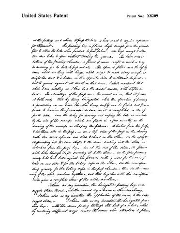 Page 6
-
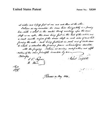 Page 7


U.S. Patent and Trademark Office · Google Patents
Show the transcription Hide (2,430 words)
Machine transcription (LightOnOCR) of the pages as scanned by the USPTO, most of them the handwritten copies made when the records were restored after the 1836 fire. Not checked; it can misread handwriting, so compare it with the scan.
Page 2.
United States Patent
Patent No.: X8209
Robert Triplett, County of Daviess, Kentucky.
Letters Patent.
The schedule referred to in these Letters Patent and making part of the same containing a description in the words of the said Robert Triplett, whereby the improvement in the machine for pressing Hay, Cotton &c.
To all to whom these presents shall come.
Be it known that I Robert Triplett of the County of Daviess and State of Kentucky, have invented a new and useful improvement in the pressing machine for pressing Cotton, Hay, and other bales, and that the following is a full and exact description of the construction and operation of the machine as invented by me, and called the Horizontal Press.
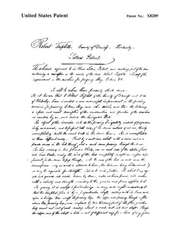
The object of this invention is to do the pressing horizontally, instead of perpendicularly, as is usual, and to press both ends of the bales instead of at one, thereby accomplishing double the usual work in the same time. This is accomplished in three different ways. First by a cast iron wheel with a screw and a female screw in the hub thereof, and a male screw passing through the same. The hub revolving in two plummer blocks, one on each side of the shaft, fixed into hear blocks, raising the hub of the hub completely except one orifice sufficient for the screw to pass through, and the ends of the hub as well as on the circumference only so much is allowed to bear (the balance being hollowed out) as may be requisite for strength. This is to avoid friction, the wheel being cogged and geared into wheels driven by steam, water or horse power, with motion with a velocity and strength according to the gearing and power applied to it. In pressing it is useless to particularize, as every one will right understand it. But the simplest plan is by a perpendicular shaft, resting with its lower end upon a bridge beam across the pressing box, the upper end passing through a floor above the pressing box, and confined by two timbers (part of the floor) with a half round cut out of each meeting about a notch cut into said shaft. Through the upper end of the shaft a hole is cut of sufficient size for a lever of any given
Page 3.
United States Patent
Patent No.: X8209
be thought to bear the power applied to it; on the said shaft below, is a wheel or a train — are lead to work into the next wheel. The upright shaft being first in motion by horses at the end of the lever, turns the vertical nut-wheel, and the screw being fastened at each end to followers, so as to prevent its rocking, it must pull to and fro, as the vertical wheel revolves, and so the pressing in boxes prepared for the purpose; at each end of the screw, see the drawing —
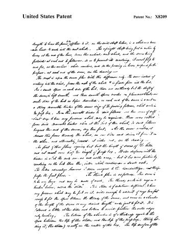
The next is upon the same plan with this difference only. The screw instead of working into the wheel, forms the axle of the wheel & is fixed firm into the hub. In a small space on each side of the hub, there are no threads but the shaft of the screw, is left smooth, and these smooth spaces revolve in plummer-blocks on each side of the hub as before described; on each end of the screw is a nut — a strong movable timber of the same size of the pressing follower, which works in the prep box. From this movable timber to said followers are two rows of sufficient stops to bear any pressure which may be required. These rows extend from said movable timber when at the side of the wheel, to said followers beyond the end of the screw, say two feet; as the screw revolves, it draws this frame towards the wheel, on one side and draws it from it on the other, and alternately presses at either end, see the drawing —
The first of these plans requires but half the length of screws of the latter and not much over half the length of prep box. It also dispenses with the timber in which the nuts are, as well as the key, — but it has more friction by rocking on the hub than the latter, which revolves on a double axle. The latter advantage, however, I seem unequal to the disadvantages, and therefore prefer the first plan. —
The third plan is as follows. This screw is to be very large and may be made of wood. The threads work into cogs in a timber below, named the “slider”. This slider is of substance sufficient to bear any pressure which may be put on it, wide enough to admit of cogs two feet deep to fit the space between the threads of the screw, and runs in a chamber of the length of the screw or any desired length made just to fit it. It is followed a little at the sides and bottom to avoid friction the outer edges only touching. The bottom of the chamber is of a thickness equal to the space between the top of the slider and the top of the prep box, thereby holding it (the slider) exactly in the centre of the box. The top surface of the
Page 4.
United States Patent
Patent No.: X8209
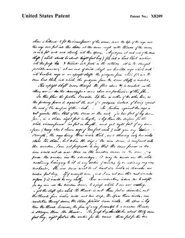
*sliver is hollowed to fit the circumference of the screw, so are the tops of the cogs, and the cogs are put into the slider at the same angle as the threads of the screw, so as to fit well and closely into the space. A quaggon at each end of the screw shaft (which should be about eight-feet long) fits into a head block which is into the prop box & turned into posts on the outside, all in the strongest possible manner; at one end of said shaft are bevelled cogs which work into bevelled cogs in an upright-shaft, the quaggon from which fits into the same head block, into which the quaggon from the screw shaft is inserted.
This upright shaft passes through the floor above & is worked as the other way — see the drawing for a more clear comprehension of this plan.
In this plan the friction I consider less than in either of the other two, as the pressing power is against the end of a quaggon instead of being against the end of the surface of the wheel... the friction against the cogs is not greater than that of the screw in the nut, for two feet of log surface, in a slider eight feet in length, is less than the surface for the whole circumference two feet in length, and yet eight feet of cog surface (being about eleven cogs of two feet each) will give any desired strength, the cogs being three inches thick, and showing only two inches above the slider, but when the size of the iron screw is compared with the wooden, I am not prepared to say that the same power on the iron would not do more than on the wooden screw, in the case of my power the wooden has the advantage, it may be made and the whole machinery belonging to it in any section of country by an ordinary engineering mechanic. The iron screw must be at least six inches in diameter and twelve feet long. If wrought iron (and I am not sure that cast iron will answer) it would be very costly. These considerations induce me to adopt for my use the wooden screw, & a prop which I am now erecting.
I get the shaft upon which the thread is cut three feet in diameter, cut the thread four inches wide and two deep, the space three inches, one revolution thereof drives the slider forward seven inches, the space is less than the thread because; the face of a cog presented to a wooden thread, is stronger than the thread. The prop box should be about thirty-seven feet long, eight-feet in the centre for the screw, three feet for the two
Page 5.
United States Patent
Patent No.: X8209
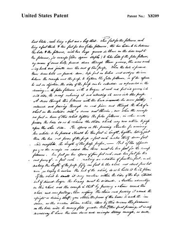
head blocks, each being a foot and a half thick. Two feet for the followers, each being a foot thick & two feet for two false followers, the two latter to be between the bale & the followers, with two large grooves in them on the side next to the followers, for cramps (like square clamps) to take hold of the false followers, by means of screw bolts; passed down through those grooves, the arms reaching back and joining over the end of the props. When the bale is pressed these screw bolts are passed down, bolts put on below and wedges driven between the cramps and the props, to tighten the false followers, or if the expense be not an objection, the sides of the props can be extended as represented in the drawing — the false followers with a tongue at each end put into grooves into said sides, the cramps embracing it and extending its arms into the props.
A screw through this follower with the head inward, the screw pointing outward and passing through an end piece and through the hub of a wheel on the outside with a screw nut therein, now when the cramps are fast on them of this wheel tightens the false followers, in other words presses the bale so as to relieve the slides which may now return to props upon the other side. The space in the pressing chamber for receiving the articles to be pressed should be ten feet in length, together twenty feet then the two end pieces of the props a foot each makes thirty seven feet.
This completes the length of the props proper. — But if the apparatus gives the cramps are added then there must be two feet for the cramps followers. One foot for two spaces of five feet each, and two feet for two end pieces of a foot each — making an addition of fourteen feet, in all making the length of the props fifty one feet to the wheel and about four feet more for boxing to enclose the hub of the wheel, so as to hold it to its place.
If the wheel be small it may revolve within the sides of the box extended but if desired larger the boxing must be widened. Another advantage in this wheel and the cramps is that by passing a chain round the wheel and over pulleys, then engaging the chain and passing it round the upright or driving shaft, you obtain the power of the horse to work the iron screws, as the wooden slides return, and by this means the pressure on the bale will be many fold greater than the foot pressing, it is only necessary to have the iron screws and cramps strong enough, as well.
Page 6.
United States Patent
Patent No.: X8209
as the pulleys and chain, to press the bale is hard as not to require reference for shipment. The pressing box is placed high enough from the ground floor to allow the bale when pressed to pass below, also high enough to allow the door below to open without touching the ground. The lower side or bottom of the pressing chamber, is floored of course except so much as may be necessary for the bale to pass out at. This space is filled as is the top by doors, which are hung with hinges, which might be made strong enough as might the doors & a button on the opposite side to withstand the pressure but to guard against all doubt on that score, I shall construct that which I am erecting as I have had the model made, with lofty an bars. The advantage of this press over the usual one is, that it presses at both ends, that by being horizontal while the operation of pressing is proceeding on one side the other being empty can be filled and prepared to receive the pressure as soon as it is completed on the opposite side, even the delay for serving and opening the bale is avoided by the aid of the cramps, which are fixed in a few minutes, as the drawing of the cramps as clasping the followers. detached from the press, I see them also in the press, — see a top view of the press in the drawing with the doors open on one side & closed on the other, see the upright shaft working into the screw shaft, & the screw working into the slide, as detached from the press box, see at the end of the slide, the follower with holes through it, for screwing it to the slide. see the pairs followers, ready to be laid loose against the followers with grooves for the cramp bolts on one side & for the baling rope on the other, see the corresponding grooves for the baling rope in the press chamber; then see the screwing of the whole machine together, and that together with the inscription will give a complete idea of the whole machine.
I claim as my invention, the horizontal pressing box and cogged slide therein, whether moved by a screw or other machinery.
I claim also as my invention the application of the screw, to the said cogged slide.
I claim also as my invention, the horizontal pressing box, with the screw passing through the hub of a wheel, which by revolving different ways causes the screw when attached to followers
Page 7.
United States Patent
Patent No.: X8209
at either end to press first at one end and then at the other.
I claim as my invention, the screw laid horizontally in a pressing box, with a wheel in the centre thereof revolving upon the screw shaft as an axle, the same being fast in the hub of the wheel, and a small smooth surface of the screw shaft on each side of said hub forming the axle — nuts being fastened on each end of said screw to which is attached the pressing power as hereinbefore described.
Also the foregoing I claim as various modifications and applications of the same principle invented by me.
Witnesses
J. W. Rogers
H. Blair
Robert Triplett
Patented 19. May 1824.
Published accounts: journal notice
Notice in the monthly list of patents, with remarks
Journal of the Franklin Institute, new ser., vol. 14 (1834), p. 402 · View the page
(See specification, at p. 341.) 31. For a Press for Cotton, and other Substances; Robert Triplett, Daviess county, Kentucky, May 19.
Remarks. The power in this machine is applied by means of an iron screw placed horizontally, and having on each of its ends a follower, which followers are alternately forced up against the article to be pressed. The screw is made to traverse backward and forward by means of an iron cog wheel, which operates as a nut, having a female screw through its centre, which fits on to the horizontal screw; a crown wheel upon a vertical shaft, gears into the teeth of the nut, or cog wheel, to give it motion, and as this nut turns between stationary collars, the screw traverses, without turning. The vertical shaft may be turned by horse, or other power. The collars, or bearings of the respective parts, we need not describe, as any competent workman will readily understand how to adapt them to the other parts. The boxes, and other provisions for forming the bales, may be similar to those generally used in cotton presses. It is intended, sometimes, to make the cog wheel fast upon the shaft of the iron screw, so that the latter may revolve without traversing backward and forward; in this case, the screw works in a nut fitted to a frame, or bale, attached to each follower, in such a manner as to allow the requisite room for the traversing of the screw between the nut and the follower. This modification of the machine, as well as its general construction, is distinctly described and claimed, and we think that there is sufficient novelty in the general arrangement, as claimed, to sustain the right of the patentee.
About this record
- Patentee
- DATAMP
- Date
- the Name and Date index of patents, DATAMP, USPTO records
- Invention
- DATAMP
- Listed in
- the Name and Date index of patents, DATAMP, USPTO records, Jim Shaw's X-patent list, the Journal of the Franklin Institute, Burke's List of Patents (1847)
- Burke's 1847 Patent Office list gives the same patent.