

Drawings and documents
National Archives restored drawings: drawing
John Davidson's Patent Drawing for an Apparatus for Shearing Cloths


National Archives, Restored Patent Drawings (Record Group 241) · Full-size scan at the National Archives · Catalog record
Show the text on the drawing Hide (124 words)
Words on the drawing as machine-read by the National Archives; not checked. Useful mainly for searching.
Sheet 1. $11- Plate I. 26. CLOTH. / [37] Shearing. / ICATION / 8225-x / VISION. / John Davidson's / Apparatus for shearing Cloths. / Patented May 29.1834. / Fig / 22 / 29 / 12 / OlR / 33 / 23 / Drawn by Francis Benne.
Sheet 2. Platel. / to / Fig2. / DIVISION. / 82 8 8225% 2 25 to / CLASSIFICATION / Patentes 34 John for / S. / Davidson / JO / 14 / 31 / 26 / 25 / apparatus shearing Clothe. / 23
Sheet 3. Plate II. / djo / cl / Fig 1. / Sheet-1- Plate 2 / sharmy / Back Elevation of Frame. / Drawn to one fourth real size. / he / NOLLVOLSISSVTO / DIVISION. / Davidson / 8225-X / Cloth Stuaring / Patentes may 29-1884
Sheet 4. Plate II. / ASSIFICATION / 8225-X / IIV ISION. / Fig2. / Longitudinal Section / Drawn full size. / Patenter Shay 29° 29°1834 1834 / Cloth showing Suchine / I Davidson / 27 / 27 / Sheetz Platoz 1 2
Sheet 5. Plate I. / ASSIFICATION / 8225.4 / BION. / Fig5. / 28. / O/R / 37 / John Davidson / apparatus for shearing Cloth / Patentes may 2921834
USPTO scan
The patent as scanned by the USPTO
-
 Page 1
-
 Page 2
-
 Page 3
-
 Page 4
-
 Page 5
-
 Page 6
-
 Page 7
-
 Page 8
-
 Page 9
-
 Page 10
-
 Page 11
-
 Page 12
-
 Page 13


U.S. Patent and Trademark Office · Google Patents
Show the transcription Hide (3,615 words)
Machine transcription (LightOnOCR) of the pages as scanned by the USPTO, most of them the handwritten copies made when the records were restored after the 1836 fire. Not checked; it can misread handwriting, so compare it with the scan.
Page 1.
BEST AVAILABLE COPY
Sheet 1 - Plate 1.
J. Davison.
Cloth Shearing Mach.
Patented May 29, 1834.
5,225 X
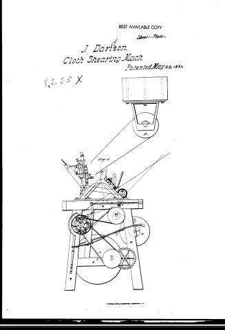
Fig. 1.
R. HETERS, PHOTO-LITHOGRAPHER, WASHINGTON, D.C.
Page 2.
BEST AVAILABLE COPY
Sheet 2. Plate 1.
J. Davison.
Cloth Shearing Mach.
Patented May 29, 1834
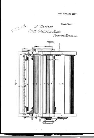
Fig. 2.
Page 3.
BEST AVAILABLE COPY
8,225 X J. Davison.
Cloth Shearing Mach.
Patented May 29, 1834.
Sheet 3-Plate 1.
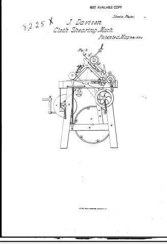
Fig. 3.
K. PETERS, PHOTO-LITHOGRAPHER, WASHINGTON, D.C.
Page 4.
Sheet 1-Plate 2.
J. Davison.
Cloth Shearing Mach. BEST AVAILABLE COPY
Patented May 29, 1834.
8225X
Fig. 1.
M. PETER, PHOTO-LITHOGRAPHER, WASHINGTON, D.C.
Page 5.
Y125X
J. Davison.
Cloth Shearing Mach.
Patented May 29, 1834.
Sheet 2 - Plate 2.
BEST AVAILABLE COPY
Fig. 2.

R. PETER, PHOTO-LITHOGRAPHER, WASHINGTON, D.C.
Page 6.
May 29, 1834
John Davidson, of Springfield, Vermont.
Letters Patent
The schedule referred to in these Letters Patent are making part of the same containing a description in the words of the said John Davidson himself, of his improvement in the machinery and apparatus for shearing broad cloths.
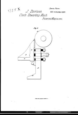
To all to whom these presents shall come, John Davidson of Springfield, in the County of Windsor, and State of Vermont, Mechanist sends greeting: Be it known that I the said Davidson have invented, made constructed, and applied to use, a new and useful improvement in the machinery and apparatus for shearing broad cloth, which I specify and describe as follows: That is to say, the machine embracing my said improvement is represented as well as distinct parts thereof, in the drawings hereto annexed, which are to be taken and considered as part of this specification. Fig. numbered one, in plate numbered one, is an end view of the machine on the left hand, and figure numbered three, in the same plate, is an end view of the end of the machine on the right hand. Figure numbered two in the same plate, is a front view of the same machine. Figure numbered one, in plate numbered two, is a representation of the ledger, or stationary blade, and the bed and back to which it is affixed, and the frame with which it is connected, whereby it is supported. Fig. numbered two, in the same plate is a sectional view of the same blade, bed and back, and frame, and the screws whereby the bed and back, with blade, is firmly held in the middle thereof. The same parts of the machine, are designated by the same letters, or numbers, in all the figures in both plates. The machine which I describe is one, which I have now in operation, and the form, dimensions, and proportions are given therefrom, but may be somewhat varied, at discretion, as a Mechanist of ordinary skill will readily perceive. A designates the ledger blade, which is made of iron and steel, in the usual way of making such like cutlery, and is about two inches wide, and about five feet nine inches long, and about three sixteenths of an inch thick, and is firmly rivetted to a piece of cast iron, which forms the bed and back thereof and is designated by C, which with the cast iron frame designated by B, by which it is supported, serves to render the blade stiff, firm, and unyielding.
Page 7.
The ledger blade laps over the pieces of cast iron which form the bed and back thereof, about five eighths of an inch. But it may be made to lap over more or less at discretion, so that the cloth is kept from touching the bed, and it may be wide or narrower, and thicker or thinner, at discretion, provided it be sufficiently thick, to be kept perfectly firm, and unyielding. The edge of this blade must be ground to resemble the edge of the blades of shears, or the edge of ledger-blades, used in the shearing of cloth, and must also be perfectly straight, and even, so that it may be exactly and nicely adjusted to the spiral blades on the rotary cutter, designated by E. The ledger blade, and the rotary cutter with its blades, are nicely adapted and fitted to each other, by grinding them at first separately, as even and straight as possible, and finally, by grinding them together against each other, so that they may be exactly and perfectly fitted and adapted to each other. The piece of cast iron designated by C, to which the ledger blade is rivetted, is about six feet five inches in length, about seven eighths of an inch thick, and of the form represented by a section thereof, in figure numbered two in plate numbered two. D, D designate braces which serve to render this bed and back for the ledger blade more firm, and unyielding, of which there are six, but they are cast with the bed and back in one solid piece of cast iron.
This bed and back may be made of wrought iron, composition metal, or metal of sufficient strength to hold and retain the ledger blade, and to keep it firm, firm and unyielding. The piece of cast iron C is fixed to the cast iron frame B, firmly, at each end, and in the middle, by the screws designated by f, f, b. The middle screw b, passes through one part of the frame B, and operates in C, and the end screw f, f, pass through the back C, and operate in the frame B. There is a slant where the screws are in the ends in C, and in the middle in B, in order that the bed and back, and its ledger blade, may be moved back and forth when requisite to adjust the edge of the ledger blade, to the blades on the rotary cutter, and put and keep it in the requisite position, for operating with these blades, in cutting. The screws e, g, at the ends, and a, c, in the middle, pass through B, and operate on C, and assist in adjusting the ledger blade to the spiral blades on the rotary cutter, and also, in causing the bed and back C, with its blade, to be steady, firm and unyielding, and to be kept so. The screws e, f, g, at the ends, and a, b, c, in the middle, must be in a line at right angles, with the edge of
Page 8.
the ledger blade II. &c. designate screws at the ends of the bed and back of the ledger blade, to raise or depress it, with the ledger blade, and to adjust in moving it, when required, and keeping it in a suitable position for cutting.
B. designates the cast iron frame, for supporting the bed, and back, with its blade and the rotary cutter. It is about six feet and five inches long, and an inch and one eighth of an inch thick, and the lower part to which the back and bed, of the ledger blade is fastened, is about four inches and an half wide, and the upper part or bar for removing the frame, upon its pivots, when required by the hand, is about two inches wide, and the ends of the frame, from the extremities, are about seventeen inches long, and two inches wide at one part of each, but wider at other parts, as represented in the figures numbered one, in plate numbered two.
The lower part to which the bed and back of the ledger blade is fastened, has parts projecting from it, designated by the figures 27. 27. to make it more stiff, strong, firm, and unyielding. Z. designates the pivots at each end, on which the frame B is turned, when it is required to remove the rotary cutter, and ledger blade from, or carry them to the cloth upon the rest A. The part of the cast iron frame V. designated by the figures 12. forms a brace or support, against which the iron frame B rests, when it is raised up, with the ledger blade, its bed & back, & the rotary cutter from the cloth on the rest A. This frame may be made of composition metal, or wrought iron, or any metal sufficiently stiff & firm, but cast iron is deemed preferable, as uniting stiffness, firmness, strength, lightness, & cheapness, as well for the bed and back of the blade, as for the frame B. The form and size of the frame B, and the bed and back C. may be somewhat varied at discretion, as any mechanic of ordinary skill will perceive, but they must be sufficiently large, to be firm, and unyielding, and adapted to hold and keep the ledger blade & rotary cutter, in a proper position for cutting & shearing, and the means of adjusting & fastening the blade with its bed & back to the frame, & the rotary cutter, & cloth to be operated upon may be somewhat varied but the means above described are deemed preferable.
It is indispensably necessary that the ledger blade, should be kept firm, and unyielding, and should be nicely & exactly adapted to the special blades on the rotary cutter. E. designates the rotary cutter, which has cast steel quodgans, having bearings in composition boxes, h.h. confined firmly to the frame B. on the side opposite to that, on which the ledger blade is. The shaft of the rotary cutter is of wrought
Page 9.
iron about three inches in diameter, and five feet and eleven inches long, having twelve spiral blades projecting beyond the shaft about half an inch, which are inserted in the shaft in the usual way. The shaft may be varied as to its diameter, or made hollow, and may be made of any metal not fusible and sufficiently firm to hold the blades, but wrought iron is deemed preferable, and the shaft ought not to be much less in diameter, otherwise it will be liable to spring. The blades may project somewhat more or less, but the above projection is deemed best, and there ought to be as many blades in the shaft, as there are quarters of an inch in its diameter. It is indispensably necessary, that the rotary cutter should be kept firm, and unyielding, and that its blades should be nicely and exactly fitted, and adapted to the edge of the ledger blade, its relative position to which when in operation, is shown in figure numbered two, in plate numbered two; on an extension of the guide-iron, at one end of the rotary cutter, is a pulley t, by a cross belt, which passes over one of the guiding pulleys 22, and over the pulley q. on the end of the shaft of the large cylindrical brush s. and between said guiding pulleys, and over the other of them. F. designates the rest for the cloth to be submitted to the operation of shearing over which rest, the cloth passes, which rest is made of cast iron, but may be made of any other suitable metal, sufficiently stiff and firm. It is fixed to the iron frames V with screws at each end, by which it is raised, lowered, and adjusted, and held firmly in its place. It is about six feet long, about four inches wide, and about three fourths of an inch thick, except the upper edge which is about one sixteenth of an inch thick, and rounded, and made perfectly straight and even, so as to correspond with the rotary cutter and ledger blade, and has the under part of the bar, extending at a right angle from the other part, in form of a lip with three braces, somewhat like the piece of cast iron c, which forms the back and bed of the blade before described. The form and size of this rest may, however, be varied somewhat at discretion, but the above is deemed preferable. On each end of this rest, there are slides numbered 1, 2, 3, 4, 5, 6, 7, 8, 9, 10, with slonghits in them, and fastened by screws, so that they may be raised or lowered to adapt the length of the rest, to the width of the cloth, to be sheared, between the lats, and save the lats. This rest should be brought within about an eighth of an inch of the ledger blade, or nearer, or more distant according to the thickness of the cloth to be
Page 10.
Sheared d. designate, a screw at each end, for regulating the distance of the rotary cutter, and ledger blade from the cloth to be sheared. K.K. are brushes to lay the nap upon the lists, so as to prevent the rotary cutter and ledger blade from operating upon it. These brushes are connected with slides, with a slought in them, so as to bring the brushes upon the lists, whether the cloth be wider or narrower. C. is another rest which keeps the cloth near to the brush for raising the nap so that this brush may operate upon it. This rest is fastened at each end by a screw to pieces of iron, with a pivot on them, and a slought in them, so as to raise or lower the rest, and turn upon the pivots, and is turned up from and down to the cylindrical brush. H. by the handle, T, is confined in its place whether up or down, by the springs. The upper side of the rest when in a position to have the cloth operated upon by the brush, should be brought in a line with the radius of the brush, and the under side is rounded off from the angle or corner near the brush. This rest should be firm and stiff, so as not to yield by the pressure of the cloth upon it. H. represents the revolving cylindrical brush for raising the nap on the cloth to be sheared. It is six feet long, about four inches in diameter, and made in the usual way, with eighteen spiral rows of brushes, and turns on gudgeons, in boxes, on the iron frames Y, and is driven by the pully M. on the end of its gudgeon with a cross belt from pully N. on the end of the shaft of the cylindrical brush L. (15) designates a wooden revolving roller with felt projecting from it to receive oil, by oiling the blades of the rotary cutter, and is caused to revolve by a band passing over a pully on the end of the roller, and thence over a pully on the end of the pivot Z. which last pully is driven by another band which passes over a pully on the end of the gudgeon of the cylindrical brush. H.T. designates a table six feet long to lay the cloth upon, while it is being put into the machine, or taken out therefrom. K. is a cylindrical scraper six feet long, consisting of a wooden roller with three pieces of iron, with round edges fixed into it, spirally, like the blades in the rotary cutter, to brush the flock from the back side of the cloth and prevent them from collecting on the edge of the rest near to the ledger blade and rotary cutter. L. designates the cylindrical brush for laying the nap, which is six feet long and nine inches in diameter, but may be varied somewhat in size at discretion, and contains thirty-six rows of brushes in a spiral form. It turns on
Page 11.
166. 8225X
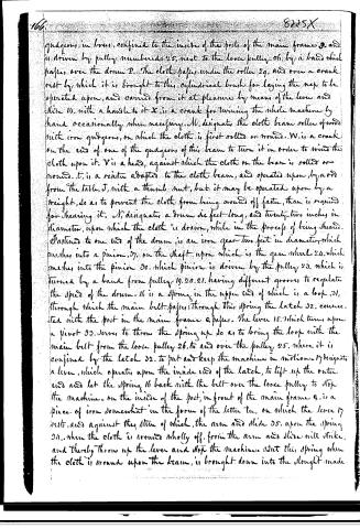
gudgeons in boxes, confined to the inside of the posts of the main frame 9, and is driven by pulley numbered 25, next to the loose pulley 26, by a band which passes over the drum P. The cloth passes under the roller 29, and over a crank rest by which it is brought to this cylindrical brush for laying the map to be operated upon, and carried from it at pleasure by means of the lever and slide 14, with a handle to it X, is a crank for turning the whole machine by hand occasionally when necessary. M, designates the cloth beam roller of wood with iron gudgeons, on which the cloth is first rolled or wound. W, is a crank on the end of one of the gudgeons of this beam to turn it in order to wind the cloth upon it. V is a head, against which the cloth on the beam is rolled or wound. t, is a reinstr adapted to the cloth beam, and operated upon by a rod from the table, J, with a thumb nut, but it may be operated upon by a weight, so as to prevent the cloth from being wound off faster, than is required for shearing it. N, designates a drum six feet long, and twenty-two inches in diameter, upon which the cloth is drawn, while in the process of being sheared. Fastened to one end of the drum is an iron gear two feet in diameter, which meshes into a pinion 37, on the shaft upon which is the gear wheel 24, which meshes into the pinion 30, which pinion is driven by the pulley 23, which is turned by a band from pulley 19, 20, 21, having different grooves to regulate the speed of the drum. 16 is a spring in the upper end of which is a loop 31, through which the main belt passes; through this spring the latch 32, connected with the post in the main frame 9 passes. The lever 15, which turns upon a pivot 33, serves to throw the spring up so as to bring the loop with the main belt from the loose pulley 26, to and over the pulley 25, where it is confined by the latch 32, to put and keep the machine in motion. 17 designates a lever, which operates upon the inside end of the latch, to lift up the outer end and let the spring 16 back with the belt over the loose pulley to stop the machine. On the inside of the post, in front of the main frame 9, is a piece of iron somewhat in the form of the letter t, on which the lever 17 rests, and against the stem of which, the arm and slide 35, upon the spring 34, when the cloth is wound wholly off, from the arm and slide will strike, and thereby throw up the lever and stop the machine. But this spring when the cloth is wound upon the beam, is brought down into the slought made
Page 12.
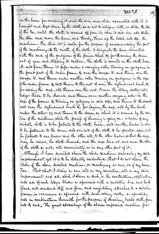
in the beam for receiving it, and the arm and slide connected with it is brought and kept down by the cloth, so as not to interfere with, or strike the stem of the tee, until the cloth is wound off from it, when it will rise and strike the stem and move the lever, and thereby throw up the latch and stop the machine. The slide 35 is made for the purpose of accommodating this part of the machinery to the width of the cloth. 11 designates the lever connected with the end of the quidgeon of the pinion wheel 27, for throwing the drum out of gear and stopping its motion. The cloth is wound on the cloth beam M, and from thence it passes under a carrying roller turning on quidgeons, in the front post of the main frame Q, near the scraper K, and thence over the scraper K, and thence under another roller turning on quidgeons, in the caps of the main frame Q, and thence to the rest G, near the cylindrical brush H, for raising the nap, and thence over the rest, G, near the rotary cutter, and ledger blade to be sheared, and thence over another carrying roller in the caps of the frame Q, turning on quidgeons in said caps, and thence to the crank rest near the cylindrical brush L, for laying the nap, and by this brush under the roller 29, and thence to the drum on which it is wound by the motion of the machine, while the process of shearing is going on. A leader of any suitable cloth is to be fastened to the cloth beam, and another leader is also to be fastened to the drum, and one end of the cloth to be operated upon, is to be fastened to one leader and the other end, to the other leader, so that the nap, may be raised, the cloth sheared, and the nap laid at, and near the ends of the cloth as well, and conveniently, as in any other part of it.
Although I have described above the whole machine, embracing my said improvement, yet it is to be distinctly understood, that I do not claim the whole of the above described machines, or machinery as new, or of my invention. But what I claim as new, and as my invention, and as my said improvement, and all, which I claim as such, is, the construction, application, and use of such ledger blade as aforesaid with a metallic bed, and back fixed, and rendered stiff and firm, and unyielding, attached to a metallic frame, in connexion as aforesaid, with such rotary cutter, as aforesaid, and in combination therewith, for the purpose of shearing broad cloth, from end to end. The great advantage of the above improved machine for
Page 13.
shearing broad cloths, that it will shear such cloths as well, and much faster, than the machines, now in common use for that purpose.
In testimony whereof I have hereunto set my hand and seal, this fifteenth day of February in the year of our Lord eighteen hundred and thirty-four.
Witnesses:
Augustus H. Fiske
Bri. Pond
John Davidson
End.
1196
Drawing
(3/28/1835)
Published accounts: journal notice
Notice in the monthly list of patents, with remarks
Journal of the Franklin Institute, new ser., vol. 14 (1834), p. 408 · View the page
In its general construction, this spindle grinder is similar to that now in general use, but the mode of connecting the lathe with the carriage, " is claimed as new, as well as the method of grinding it as it moves on the carriage. From the centre of the carriage, or about the centre, lengthwise, and near the edge of it next the grindstone, a stud, or pivot, extends upwards, which is fast in the carriage, but moves easily in a slot in the lathe. The lathe might be turned entirely round on this, were it not for other parts of the machine; its object is to permit it to be partly turned as it moves on the carriage, and at the same time to give it the same motion forward and backward that the carriage has." Weights are used to keep the carriage regularly against the track, and to aid in keeping the latter steady; the use of these is claimed. 47. For an improvement in the Machinery for Shearing Broad Cloths; John Davidson, Springfield, Windsor county, Vermont, May 29.
Remarks. The whole of this machine is very fully described, references being made to well executed drawings, one-fourth of the size of the actual apparatus. The claim is in the following words: "Although I have described above the whole machine, embracing my said improvements, yet it is to be distinctly understood that I do not claim the whole of the above described machine as new, or of my own invention. But what I claim as new, and all which I claim as such, is, the construction, use, and application of such ledger blade as aforesaid, with a metallic bed and back, fixed and rendered stiff, firm, and unyielding, attached to a metallic frame, in connexion, as aforesaid, with such rotary cutter as aforesaid, and in combination therewith for the purpose of shearing broad cloths from end to end. The great advantage of the above improved machine for shearing broad cloth cloths, is, that it will shear such cloths as well, and much faster, than the machinery now in common use for that purpose." It will be seen that this machine is from the same neighbourhood as that described in No. 12 for this month, and they have much the appearance of having sprung from the same seed.
About this record
- Patentee
- DATAMP
- Date
- the Name and Date index of patents, DATAMP, USPTO records
- Invention
- DATAMP
- Listed in
- the Name and Date index of patents, DATAMP, USPTO records, Jim Shaw's X-patent list, the Journal of the Franklin Institute, Burke's List of Patents (1847)
- Burke's 1847 Patent Office list gives the same patent.