

Drawings and documents
National Archives restored drawings: drawing
J.P Stabler's Patent Drawing for a Pneumatic Breast Pump

National Archives, Restored Patent Drawings (Record Group 241) · Full-size scan at the National Archives · Catalog record
Show the text on the drawing Hide (91 words)
Words on the drawing as machine-read by the National Archives; not checked. Useful mainly for searching.
Surgical Apples / 128. STRGERY. / J.P. STABLER'S / [156] Breast Pamps / Pneumatie Breast Pump. / Surgical- Aipples X Patented June 19th 1834. / #1- / CLASSIFICATION / L M / 8274.X / LIVISION. / Fig.1. / +B / is / Fig. Fig. 2. / AS / caoutchous K the / on the stud / Spacefor play of palse / ralreMplate / Vap fitting / held byfriction / Fig4 / Medow / Vig I not refered to in speci tion / I.T / Imi roto that of the operating / thoung another form of valne / office- deposited in the Patent / Гід.3. / N. / Indiasmber
USPTO scan
The patent as scanned by the USPTO
-
 Page 1
-
 Page 2
-
 Page 3
-
 Page 4


U.S. Patent and Trademark Office · Google Patents
Show the transcription Hide (1,056 words)
Machine transcription (LightOnOCR) of the pages as scanned by the USPTO, most of them the handwritten copies made when the records were restored after the 1836 fire. Not checked; it can misread handwriting, so compare it with the scan.
Page 1.
8274X
J.P. Stabler,
Breast Pump.
Patented June 19, 1834.
Fig. 1.
Fig. 2.
Fig. 3.
Fig. 4.
AM. PHOTO-LITHO. CO. N.Y. (OSBORNE'S PROCESS)
Page 2.
June 19, 1834
James P. Stabler of Sandy Spring, Maryland,
Letters Patent
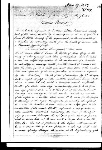
The schedule referred to in these Letters Patent and making part of the same, containing a description in the words of the said James P. Stabler himself of his improvement in the construction of a machine for extracting milk from the breasts of women called a Pneumatic breast-pump.
To all to whom these presents shall come
Be it known that I James P. Stabler of Sandy Spring in the County of Montgomery and State of Maryland, have invented a new and useful improvement in the construction of a machine for extracting or drawing milk from the breasts of women, and that the following is a full and exact description of the construction and operation of the said machine as invented or improved by me, to wit:
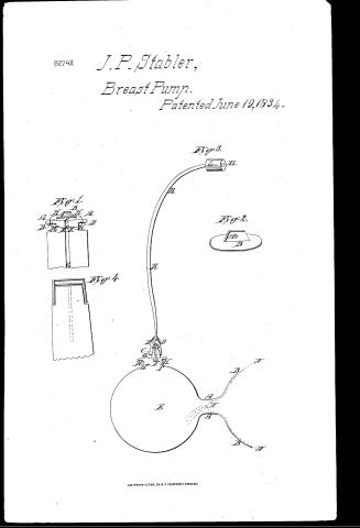
In the plate of drawings fig 3, B represents a vessel of glass or other suitable substance, having attached thereto a neck A, A, with a trumpet mouth or flange. B, B, of a shape and size, corresponding nearly to the form and size of the nipple and to that part of the female breast including and contiguous to the areola. On the top and side of the vessel is another short neck P, P, made for the purpose of attaching to the vessel the apparatus for exhausting the vessel of air, when the machine is used, which neck is left open in the construction of the vessel. H, H, represents a cap of metal or other suitable material resembling the cover for the object glass of a common telescope. The top part of this cap is perforated with a small hole at D, and with a larger hole above the letter E. This cap is fastened to the vessel with cement. E, C, is a small tube of metal fastened to the cap at E with a small opening through its centre at C longitudinally of the
Page 3.
piece. This tube is seen enlarged in fig 1. D,D, is a tube of metal or other substance fitting over the tube F,C, air tight. To the upper end of this tube a gum elastic pipe or tube K,K, is attached [num. 1] terminating in a mouth piece L, of bone, ivory, or other substance having a hole through it at all, J, is a small valve fastened by a string to the upper end of the tube F,C, (seen enlarged in fig 2, in perspective) it is composed of a circular plate of metal B fig 2, to which is attached another thin piece of metal A at right angles, and nearly central with the piece B, it has a small hole at a, through which a string passes to confine it to its place. Fig 1 represents the tube F,C, and the valve J of figure 3. At G,G, fig 1 is a small hole closed by the valve B, when it falls upon the smooth surface A,G,A, the upper surface A,A, of the tube and the lower surface of the valve are ground so as to fit closely, H,H,H,H, is a string which passes through the hole B of the valve and through two small holes D,D, of the tube and tied round the neck H,H, at F,F, of the tube. The elasticity of this string suffices the valve to open and close when in use.
A Method of using
The mouthpiece a,a,b,b, fig 3, being placed directly over the nipple a,a, (a portion of the breast being represented by the dotted lines a',a',a') and pressed gently towards the breast, the operator applies her mouth to the part L, (covering the hole m) at the same time covering the small hole G, of the cap H,H, with the thumb or finger of the hand, by which she holds the instrument to the breast, upon sucking or drawing at the mouth piece L a portion of air contained within the vessel E ascends through the orifice F of the tube F,C, opens the valve J, and passing through the pipe K,K, reaches the mouth of the operator; as soon as the operator ceases to draw the valve J shuts down and prevents the admission of the external air within the vessel. This
Page 4.
8274X 6%
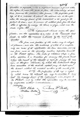
operation is repeated until a sufficient vacuum is formed within the orifice, to cause the milk to flow, the valve closing at each time, preserving the vacuum then formed. The perforation of the cap at G, is intended to admit the external air to the orifice when the drawing power of the instrument is too great for the patient to bear, and to remove it without pain from the breast. This is effected by raising the thumb, or finger, which cover the small orifice G.
The improvement claimed under this specification, are the application of a valve to the Pneumatic breast pump, in which the vacuum is formed by the mouth of the operator.
The form and position of the valve, may be changed at pleasure, and also the material of which it is composed, only one mode of its application has been described, and only one form used in the operating machine deposited herewith in the Patent Office. The valve of whatever shape or form when applied, to a machine for drawing the female breast where the mouth of the operator is used for forcing the vacuum, is therefore claimed, by which the instrument having been exhausted to the desired extent, may be kept upon the breast without the constant exertion of the mouth, of the operator.
2ndly. The perforation of the cap or orifice by which means the external air may be admitted to diminish the drawing power of the instrument, when painful to the patient, and by which the operation may be immediately suspended without inconvenience.
Witnesses
Robert Clarke & Oliver P. Habler
William Mallon
1065 - 95
Expt. 11/10
Published accounts: journal notice
Notice in the monthly list of patents, with remarks
Journal of the Franklin Institute, new ser., vol. 15 (1835), p. 43 · View the page
41. For a Pneumatic Breast Pump; James P. Stabler, Sandy Spring, Montgomery county, Maryland, June 19.
Remarks. A glass vessel, having two openings into it, is, in order to its producing the intended effect, to be exhausted of its air by the action of the mouth. One of the openings is to be applied to the breast in the usual manner, and the other is to have a cap cemented on to it, to receive the end of a flexible tube, the outer end of which is to be applied to the mouth. A valve is contained within the juncture of the flexible tube with the cap of the glass vessel, which valve, of course, opens upwards; the construction of it is particularly explained, but is spoken of as susceptible of variations. Through the cap there is a small opening, which is to be covered by the finger whilst the instrument is in use, the withdrawal of the finger allowing it to be removed readily from the breast. "The improvements claimed are, the application of a valve to the pneumatic breast pump, in which the vacuum is formed by the mouth of the operator; and the perforation of the cap, or vessel, by which means the external air may be admitted to diminish the drawing power of the instrument, when painful to the patient, and by which the operation may be immediately suspended, without inconvenience."
About this record
- Patentee
- DATAMP
- Date
- the Name and Date index of patents, DATAMP, USPTO records
- Invention
- DATAMP
- Listed in
- the Name and Date index of patents, DATAMP, USPTO records, Jim Shaw's X-patent list, the Journal of the Franklin Institute, Burke's List of Patents (1847)
- Burke's 1847 Patent Office list gives the same patent.