

Drawings and documents
National Archives restored drawings: drawing
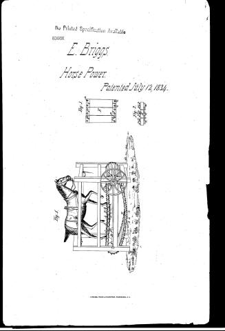
Eliakim Brigg's Patent Drawing for a Machine for Producing Horse Power

National Archives, Restored Patent Drawings (Record Group 241) · Full-size scan at the National Archives · Catalog record
Show the text on the drawing Hide (106 words)
Words on the drawing as machine-read by the National Archives; not checked. Useful mainly for searching.
185. MECHANICAL MOTORS. / Horse-Powers, / 12- / ow. Eve. Storse Powers / CLASSI / 8308.X / DIVISION. / Eliahim Briggs / Horse Power. / Patented 12 July 1834 / Fig 1 / Iig / KT / dio / Fis.1 The Machine in opera tionAdriving shafte B supporting shaft. C Wheel with cops D.D Wheelwith flange E. The floor aa de iron staples b.b.Xe ironplates / c.c.Ke iron links / Fig2 Sideview of part of the floor. / Patent office 23 June 18. / Fig 3 Top views tapart of the floor. / Made under the direction of the Con / of Patents in in conformity with act 3 Mar / A. S. illnory
USPTO scan
The patent as scanned by the USPTO
-
 Page 1
-
 Page 2
-
 Page 3
-
 Page 4


U.S. Patent and Trademark Office · Google Patents
Show the transcription Hide (916 words)
Machine transcription (LightOnOCR) of the pages as scanned by the USPTO, most of them the handwritten copies made when the records were restored after the 1836 fire. Not checked; it can misread handwriting, so compare it with the scan.
Page 1.
No Printed Specification Available
8308X
E. Briggs
Horse Power
Patented July 12, 1834.

Page 2.
July 12, 1834
8308X Eliakim Briggs.
Letters Patent.
The schedule referred to in these Letters Patent, and making part of the same, containing a description in the words of the said Eliakim Briggs, himself, of his improvement in propelling machinery by horse power.
To all to whom these presents shall come.
Be it known that I Eliakim Briggs, of the town of Port Covington in the county of Franklin and state of New York, have invented a new and useful improvement in the mode of propelling machinery by means of horse power, and that the following is a full and exact description of the construction and operation of the said machine as invented by me. I construct a strong frame of timber of oblong figure of sufficient length to give the horse room to exercise his limbs freely in stepping within it, about eight feet long, more or less, the width sufficient to contain one or more horses abreast, as the case may require, and high enough to give room to the machinery herein after to be described or specified. Across this machine or at right angles with the length thereof are two shafts of iron of sufficient strength to sustain the weight of the horse or horses together with all the strength the horse will in propelling the machinery. One of these shafts may be called the driving, and the other the supporting shaft. The shafts are so constructed and fitted as to turn in proper boxes, and the end of the driving shaft which projects from the one side of the frame, is the driving or main wheel which communicated the power either by a strap or by cogs on the driving shaft are also two strong wheels of best iron or other proper substance, say fifteen in diameter and about two inches in thickness, both more or less. The two wheels are situated immediately within the frame, on the one side of the
Page 3.
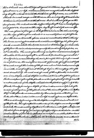
Two wheels are short cogs at equal distances, say six inches apart, more or less, as circumstances may direct. On the supporting shaft, which is near the back end of the frame, are also two wheels in each range with those on the driving shaft, and similar to them in diameter and thickness. But instead of cogs on the surface, the wheels on the supporting shaft have each a flange or a groove, round on the edge, say half inch high more or less. The use of said flange is to keep the chain on the wheel; resting on the edge of these four wheels is a movable floor or platform for the horse to walk upon, and so constructed that instead of the horse moving forwards as he continues stepping, the floor goes back wards while the horse remains stationary, by which motion of the floor the said wheels, and consequently the machinery to be propelled, are set in motion. The mode of sustaining said floor and communicating its motion to the driving shaft and thence to the machinery, and which I hereby claim as constituting the main principle this my improvement is as follows:—The said floor consists of planks of sufficient length to reach across the inside of the frame about six inches more or less in width, and of sufficient thickness to give the necessary strength and durability. On each end of each of these planks, is inserted an iron staple, which staples are turned twice at right angles, and the two ends passing through the planks and through a plate of strong iron, with a nut on each end of the staple which holds the plate or cap firmly to the plank, thereby forming a staple of three inches more or less in length, and projecting clear of the plank about the diameter of the wire. By these staples the planks are connected together side by side with strong iron links, about three inches inside more or less, reaching from one staple to the other, and thereby forming with the staples, a complete chain at each end of the planks. The caps or plates on the ends of the staples, are as long as a staple and link, the ends meeting together when the chain is straight, which prevents the chain from swaying, forming a self-supporting or arch chain—and this continuation of planks is extended so as to form an entire belt or band embracing both wheels within the said chain inside, and as the said chain
Page 4.
chain passes over the said wheels, they are made to revolve and with them the main propelling wheel which moves the machinery, and said staples as they project below the links, run in said grooves in the edge of the said wheel and keep the chain and planks steady in their places. I certify that the foregoing is a true and correct description of my said invention. I have hereunto set my hand in Fort Washington aforesaid, on the twenty-fifth day of June, in the year of our Lord one thousand eight hundred and thirty-four.
Witnesses
J. Longdon
G. S. Carpenter
Oleakin Briggs.
Drawing
(Patented March 6, 1833)
Published accounts: journal notice
Notice in the monthly list of patents, with remarks
Journal of the Franklin Institute, new ser., vol. 15 (1835), p. 99 · View the page
21. For propelling machinery by Horse Power; Eliakim Briggs, Fort Covington, Franklin county, New York, July 12.
Remarks. This is the common, inclined, movable floor, upon which the horse is to walk. The cross slats are to be connected together by staples and links on their under sides, which, by their bearing against each other, as the floor becomes straight, are to sustain it, with the horse, or horses, upon it. The doing this by means of the staples and links, is the part claimed as an improvement. There are at least two existing patents for sustaining such a floor, without ways between the drums at the ends; in both these instances, however, blocks, or stops, attached to, and rising to some height above, the upper sides of the slats, were to be brought into contact by the straightening of the floor. This latter method is undoubtedly preferable to that designated in the foregoing patent, but neither of them can be safely depended upon, with the weight of a horse upon the floor, as it is subjected to a leverage which will, sooner or later, cause them to fail.
About this record
- Patentee
- DATAMP
- Date
- the Name and Date index of patents, DATAMP, USPTO records
- Invention
- DATAMP
- Listed in
- the Name and Date index of patents, DATAMP, USPTO records, Jim Shaw's X-patent list, the Journal of the Franklin Institute, Burke's List of Patents (1847)
- Burke's 1847 Patent Office list gives the same patent.