

Drawings and documents
USPTO scan
The patent as scanned by the USPTO
-
 Page 1
-
 Page 2
-
 Page 3
-
 Page 4


U.S. Patent and Trademark Office · Google Patents
Show the transcription Hide (1,248 words)
Machine transcription (LightOnOCR) of the pages as scanned by the USPTO, most of them the handwritten copies made when the records were restored after the 1836 fire. Not checked; it can misread handwriting, so compare it with the scan.
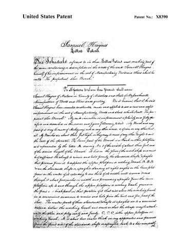
Page 2.
United States Patent
Patent No.: X8390
Samuel Haynes
Letter Patent
The Schedule referred to in these Letters Patent and making part of the same, containing a description in the words of the said Samuel Haynes himself of his improvement in the art of Manufacturing Boots and Shoes which he calls “The perpetual Shoe Bench.”
To all persons to whom these Presents shall come
Samuel Haynes of Salem in County of Middlesex and State of Massachusetts, Manufacturer of Boots and Shoes sends greeting. Be it known, that I, the said Samuel Haynes have invented, constructed, made and applied to use a new and useful improvement in the art of Manufacturing Boots and Shoes which I call “The perpetual Shoe Bench.” My said invention or improvement is plainly and fully specified and described in the words and figures following, to wit: My Bench and any part of it may be made of Mahogany, oak or any other wood, or of iron or any other metal. My Benches are about three feet high, or they may be made of any other height to suit the taste of the operator. The lower part of the Bench is a plank or other platform as is represented by the letter A, drawing No. 1 of the width of about three feet, and of the desired length of the Bench. It lies on the floor of the workshop and must be of sufficient thickness to receive and hold firmly the standards, shafts, uprights that proceed from it to support the upper platform or working Bench, B. B. B. D are the standards, shafts or uprights standing at right angles on the lower platform on the centre of it extending to one third of its width, well secured to and through it about four inches in width and proceeding upright from the lower platform up to and through the upper platform or working bench grooved in the front and back part in that portion of it that rises above the working bench in a convenient manner to receive and hold firm the heel and fore part of the shoe. The centre parts of these standards, shafts or uprights are to a convenient distance below the working bench cut down so that the straps may be attached to the shoe and play easily and freely. C, C, C, is the upper platform or working bench. It is about two inches thick in my apparatus and proceeds from the front side of the standards, shafts or uprights back to a line even with the
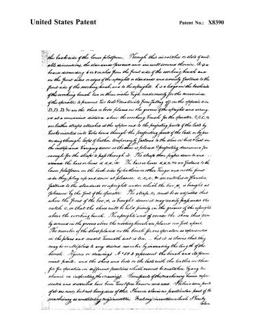
Page 3.
United States Patent
Patent No.: X8390
the back side of the lower platform. Through this in notches or slots of suitable dimensions, the standards or pieces are well secured therein. A is a board descending 6 or 8 inches from the front side of the working bench and on the front sides or edges of the uprights or standards and securely fastened to the front side of the working bench, and to the uprights. b, is a ledge on the back side of the working bench two or three inches high made merely for the convenience of the operator to prevent his tools or materials from falling off on the opposite side. D, D, D, &c are the shoes or boots placed on the grooves of the uprights and arranged at a convenient distance above the working bench for the operator. C, C, C, &c are leather straps attached at the upper end to the projecting parts of the lasts by hooks inserted into holes bored through the projecting parts of the lasts, or by proceeding through loops of leather temporarily fastened to the shoe or boot & last on the instep and hanging down as the shoe is placed & projecting downward far enough for the straps to pass through it. The straps then pass down to and around the bars or levers a, a, a, &c. The bars or levers a, a, a, &c are fastened to the lower platform on the back side by leathers or other hinges and on the front side they play up and down at pleasure. e, e, e, &c are catches or flanges, fastened to the standards or uprights under which the bar, a, is brought at pleasure by the foot of the operator. The strap e, must be so adjusted that when the front of the bar, a, is brought down it may readily pass under the catch e, so that the shoes will be held firmly in the grooves of the uprights above the working bench. The uprights and of course the shoes thus firmly secured in the grooves above the working bench are placed one foot apart. The number of the shoes placed on the bench for one operation as represented in the plans and model herewith sent is ten, — but it is obvious that they may be multiplied to any desired number by increasing the length of the bench. Figures or drawings N° 1 & 2 represent the bench and its prominent parts — and the shoes and boots or the lasts with the leathers on them fit for operation in different positions which cannot be illustrated by any mechanic in inspecting the drawings. Some parts of the machinery herein represented and described have been heretofore known and used. I believe some parts of it are new, but not being sure of this, I herein claim no particular part of the machinery as constituting my invention. But my invention is such I hereby
[Signature]
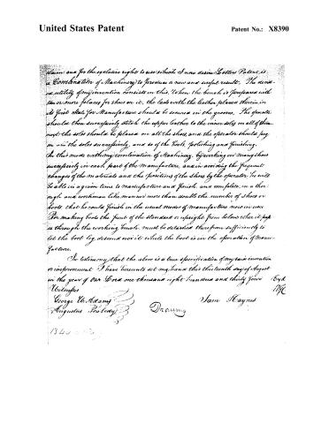
Page 4.
United States Patent
Patent No.: X8390
claim and for the exclusive right to use which I now desire Letters Patent, is a Combination of Machinery to produce a new and useful result. The decisive utility of my invention consists in this. When the bench is prepared with ten or more places for shoes on it, the lasts with the leather placed therein, in its first state for Manufacture should be secured in the grooves. The operator should then successively stitch the upper leather to the inner soles on all of them; next the soles should be placed on all the shoes, and the operator should peg on all the soles successively, and so of the heels, polishing and finishing.
In this mode with my combination of Machinery, by working on many shoes successively in each part of the Manufacture, and in avoiding the frequent changes of the materials and the positions of the shoes by the operator, he will be able in a given time to manufacture and finish, and complete, in a thorough and workmanlike manner more than double the number of shoes or boots, that he could finish in the usual modes of manufacture now in use.
For making boots the front of the standard or upright from below when it passes through the working bench, must be detached therefrom sufficiently to let the boot leg descend over it while the boot is in the operation of Manufacture.
In testimony that the above is a true specification of my said invention or improvement I have hereunto set my hand this thirteenth day of August in the year of our Lord one thousand eight hundred and thirty four.
Witneses
George W. Adams
Augustus Peabody
Sam Haynes
Drawing
1343
Published accounts: journal notice
Notice in the monthly list of patents, with remarks
Journal of the Franklin Institute, new ser., vol. 15 (1835), p. 246 · View the page
1. For a Perpetual Shoe Bench; Samuel Haynes, Malden, Middlesex county, Massachusetts, September 1.
Remarks. A long bench is to be made, which may be about three feet high; and from a platform on the floor, a row of standards, or uprights, are to extend up, through this bench, projecting above it to a sufficient height to receive the last in a notch, made for that purpose, on its upper end. These standards are to be about a foot apart, and for one workman there may be ten, or more, of them. Straps are to extend from the lasts, through holes in the bench, their lower ends being attached to treadles near the floor; then, by placing the foot upon a treadle, the strap is strained so as to hold the last firmly down, and by slipping the treadle under a cleat, it becomes fixed. Shoes or boots which are to be wrought upon, are placed on the lasts, and all of them confined in the same position, each in its own standard; this is to enable the workman to pass from one to the other, alternately performing the same operation upon each, and thus avoiding the necessity of a frequent change of tools and position. The patentee says that, "in this mode, the operator will be able, in a given time, to manufacture and finish, in a complete, thorough, and workmanlike manner, more than double the number of shoes that he could in the usual mode of manufacturing." "Some parts of the machinery herein represented and described, have been heretofore known and used;-I believe some parts of it are new; but not being sure of this, I claim no part of the machinery as constituting my invention; but my invention, which I hereby claim, and for the exclusive right of which I now desire letters patent, is, a combination of machinery to produce a new and useful re"sult." Although there certainly is no great portion of invention in this contrivance, we think that there is sufficient novelty in it to sustain a patent, which will be very valuable, if its utility is equal to, or approaches in amount, that stated by the patentee.
About this record
- Patentee
- DATAMP
- Date
- the Name and Date index of patents, DATAMP, USPTO records
- Invention
- DATAMP
- Listed in
- the Name and Date index of patents, DATAMP, USPTO records, Jim Shaw's X-patent list, the Journal of the Franklin Institute, Burke's List of Patents (1847)
- Burke's 1847 Patent Office list gives the same patent.