

Drawings and documents
National Archives restored drawings: drawing
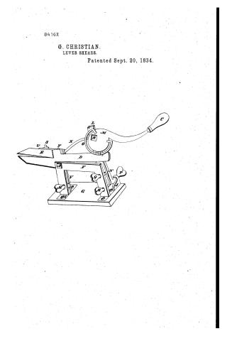
George Christian's Patent Drawing for Lever Shears

National Archives, Restored Patent Drawings (Record Group 241) · Full-size scan at the National Archives · Catalog record
Show the text on the drawing Hide (37 words)
Words on the drawing as machine-read by the National Archives; not checked. Useful mainly for searching.
64. ШЕТАЬ FUNCHING is STARING. / Sheers. Lever and Sliding. / return / p1. / GEORGE CHRISTIAN'S / CLASSIFICATION / 8416-+ / Lever Shears. / DIVISION. / Patented 20th Septemb 1834. st
USPTO scan
The patent as scanned by the USPTO
-
 Page 1
-
 Page 2
-
 Page 3
-
 Page 4


U.S. Patent and Trademark Office · Google Patents
Show the transcription Hide (1,206 words)
Machine transcription (LightOnOCR) of the pages as scanned by the USPTO, most of them the handwritten copies made when the records were restored after the 1836 fire. Not checked; it can misread handwriting, so compare it with the scan.
Page 1.
8416X
G. CHRISTIAN.
LEVER SHEARS.
Patented Sept. 20, 1834.

Page 2.
Sept 20, 1884 8416X 259
George Christian of Muntz Baguga Co., New York
Letters Patent.
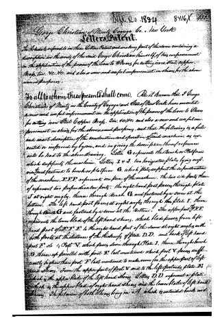
The Schedule referred to in these Letters Patent and making part of this same containing a description in the words of the said George Christian himself of his improvement in the application of the powers of the lever to Shears for cutting iron, Steel, Copper, Brass, Tin, &c. &c. and also a new and useful improvement in shears for the above named purposes.
To all to whom these presents shall come. Be it known that I George Christian of Muntz in the County of Baguga and State of New York have invented a new and useful improvement in the application of the powers of the lever to Shears for cutting iron, Steel, Copper, Brass, Tin, &c. &c. and also a new and useful improvement in shears for the above named purposes, and that the following is a full and exact description of the construction and operation of said machine, as invented or improved by by me, and in giving the description thereof reference will be had to the above drawing. Letter G represents the Bench or Platform which supports the machine. Letters I & J, two horizontal plates, lying cross-wise and fastened to bench or platform G, which plates support the construction of the machine. F.F.F. represents one piece of the machine. The two side parts thereof represent two perpendicular posts. The right hand post passes through plate J at right angles, thence through Bench G, and fastened by a screw at the bottom. The left hand post passes at right angles through the plate I, thence through Bench G and fastened by a screw at the bottom. The upper part F.F.F. represents the lower blade of the left hand shears, which blade passes from left hand post of F.F.F. to the right hand post of the same at right angles with both posts at the distance of the thickness of plate D.D. and back of left hand post F. to a Post V, which passes down through Plate I, thence through bench G, thence up parallel with post F last mentioned which post V passes sufficiently higher than post F last mentioned to make room for the upper part of left hand shears. From the upper part of post V and to the left foreends plate D, which is the upper blade of the left hand shears. Letters D.D. represent a plate which is the upper blade of right hand shears and the lower blade of left hand shears. The fulcrum of both shears being in A, which is extended back and
Page 3.
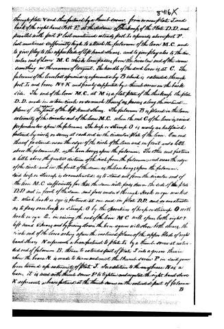
through plate V and then fastened by a thumb-screw, from near plate J, and back of the right hand post F, at the distance of the thickness of the plate D.D. and parallel with post F last mentioned extends post I, upwards above post F last mentioned sufficiently high to attach the fulcrum of the lever M.C. and to give play to the upper blade of left hand shears, and to give play also to the circular end of lever M.C. which lever passes from the circular end of the same something in the manner of tangent. The handle of the said lever is at C. The fulcrum of the lever last aforesaid is represented by B which is extended through post I, and brace N & K and firmly supported by a thumb-screw on the back side. The end of the lever M.C. at M is a flat plate of the thickness the plate D.D. made in a true circle or so much thereof as passes along the inclined plane of the upper part of the left hand shears. The fulcrum B is placed in the lower extremity of the circular end of the lever M.C. when the end C of the lever is raised perpendicular upon the fulcrum. The hoop or stirrup O is nearly an half circle fastened by rivets or screws at each end in the circular plate of the lever. One end thereof is fastened near the edge of the circle of the lever and in front and a little above the fulcrum B, as the lever hangs upon the fulcrum. The other end fastens a little above the greater distance of the circle from the fulcrum, and near the edge of the circle and in the front of the same as the lever hangs upon the fulcrum. Said hoop or stirrup is so constructed as to stand out from the circular end of the lever M.C. sufficiently far that the same will pass down the side of the plate D.D. and in front of the same, and pass under & through hook or eye marked 2, which hook or eye is fastened at one end in plate D.D. and so constructed as to pass over hoop or stirrup O by the operation of hoop or stirrup O with hook or eye 2, in raising the end of the lever M.C. will open both right & left hand shears and by forcing down the lever again will close both shears. The circular end of the lever acting upon the inclined plane of the upper blade of right hand shears N represents a brace fastened to plate I, by a thumb-screw at extended end of fulcrum B, thence to extended part of plate J into a groove therein when the brace N is made to turn and meet the thumb-screw P in said groove from turned up extremity of plate J. In addition to the one brace N as a brace, it is used with thumb screw P to tighten and regulate the right hand shears K represents a brace fastened at the thumb screw on the extended part of fulcrum B
Page 4.
8416 X
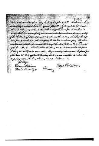
there to the screw T. There along the back side plate T to V. S represents a thumb screw through extended brace K, against plate D, which regulates left hand shear. H represents a thumb screw which supports, stand feet D and foot V. between both last named feet, and around said last mentioned screw is a stay of the thickness of plate D.D. R & Q represent thumb screws which pass thru left hand feet D and foot V, which supports the two last mentioned feet. The whole machine is constructed of iron and steel except bench or platform & and handle of the lever M. C. I claim that the shears are constructed so that two pairs of shears are contained in one machine, being a new improvement, and the principle of the lever M. C. is applied to the shears which is a new invention, as well as the ways of regulating the shears which is also a new improvement.
Witnesses
Denison Robinson
David Varnilga
George Christian
Drawing
Published accounts: journal notice
Notice in the monthly list of patents, with remarks
Journal of the Franklin Institute, new ser., vol. 15 (1835), p. 259 · View the page
27. For Shears for Cutting Metal; George Christian, Mentz, Cayuga county, New York, September 20.
Remarks. If a pair of shears of the ordinary form be taken, and the handles converted into blades, there will then be shears on each side of the fulcrum; and such is the case with those which form the subject of this patent. A lever fixed upon the frame which holds the shears, serves to force one of the blades down by means of an eccentric. The frame, braces, thumb screws, &c., are particularly described; but we find nothing in these worthy of special notice, or any result obtained by them which could not be accomplished equally well in other ways. The claim is, "that two pair of shears are constructed in one machine, being a new improvement; and the principle of the lever, MC, [referring to the drawing,] is applied to the shears, which is a new invention, as well as the ways of regulating the shears, which is also a new improvement." If the two pairs of shears could be worked with the same power as one, this would not have been merely a new, but really a very great and a very useful improvement; but, as the matter stands, it appears to us that the novelty far outweighs the utility.
About this record
- Patentee
- DATAMP
- Date
- the Name and Date index of patents, DATAMP, USPTO records
- Invention
- DATAMP
- Listed in
- the Name and Date index of patents, DATAMP, USPTO records, Jim Shaw's X-patent list, the Journal of the Franklin Institute, Burke's List of Patents (1847)
- Burke's 1847 Patent Office list gives the same patent.