

Drawings and documents
National Archives restored drawings: drawing
Garet G. Heermance's Patent Drawing for an Improvement in the Construction of Water Wheels

National Archives, Restored Patent Drawings (Record Group 241) · Full-size scan at the National Archives · Catalog record
Show the text on the drawing Hide (167 words)
Words on the drawing as machine-read by the National Archives; not checked. Useful mainly for searching.
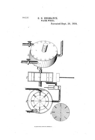
188.HYDRAUL / Rotary MOTOR Hy Engines / Garet I. Hurmance / CLA 43. PICATION / 8.423X / Improvement in the construction of Water wheels / ofig.1. Sept. 30, 1834 / DIV ISION. / Tig 3 / stigh / ted Heps ted / Pata & Sept. 30, 183 / Reference a hollow cylinder b the wheel / k' betoffhole l. foreing pump. / c.c.e.te packing did d d. d, d. d. the / Big i. section of cylinder pipes, blocks and pump, / values. eceeeeee, rods I.I side plates of / the wheel seen from the side. / cylinder a. - g g shaft of wheel. h h / Sig 2. Section of wheel b. / Patent office soth Leptember 1841 / metallic blocks. i.i holes to admit / Sig.3 Section of cylinder and a front view of / made under the direction of the Commissioner of / the water. KK pipes & stop cocks. / the wheel and values. / Patents in conformity with act of 3' march 1837 / of wheel / sigh Perspective viewofwheel. / ann ficit. / Menry L Symoth / Commissioner of Patents.
USPTO scan
The patent as scanned by the USPTO
-
 Page 1
-
 Page 2
-
 Page 3
-
 Page 4


U.S. Patent and Trademark Office · Google Patents
Show the transcription Hide (1,054 words)
Machine transcription (LightOnOCR) of the pages as scanned by the USPTO, most of them the handwritten copies made when the records were restored after the 1836 fire. Not checked; it can misread handwriting, so compare it with the scan.
Page 1.
8423X
G. G. HERMANCE.
WATER WHEEL.
Patented Sept. 30, 1834.
THE NORRIS PETERS CO., PHOTO-LITHO., WASHINGTON, D. C.
Page 2.
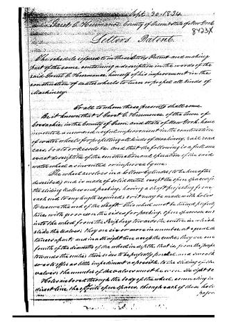
Sept. 30, 1834
Sarah E. Heermanee, County of Green, State of New York. 8423X
Letters Patent.
The schedule referred to in these Letters Patent and making part of the same, containing a description in the words of the said Sarah E. Heermanee, himself of his improvement in the construction of water wheels to turn or propel all kinds of machinery.
To all to whom these presents shall come.
Be it known that I Sarah E. Heermanee, of the Town of Bowditch, in the County of Green, and State of New York, have invented a new and useful improvement in the construction of water wheels for propelling all kinds of machinery, rail road cars, boats or vessels &c. and that the following is a full and exact description of the construction and operation of the said water wheel as invented or improved by me.
The wheel revolves in a hollow cylinder (to be hereafter described) and is made of solid metal, except the open spaces for the sliding valves and packing, having a shaft projecting from each end to any length required; or it may be made with holes to receive the end of the shaft. This wheel must be turned perfectly true, with grooves on the sides for packing. Open spaces are into the wheel from the periphery towards the center, in which slide the valves; they are six or more in number, at equal distances apart, and in a straight line near the center; they are one fourth of the diameter of the wheel in depth, that is, from the periphery towards the center, their sides to be perfectly parallel, and smooth so as to offer as little impediment as possible, to the sliding of the valves; the number of the valves must be even, the right side holes are bored through the body of the wheel, as much as in a straight line, the opposite open spaces, through each of these holes
page
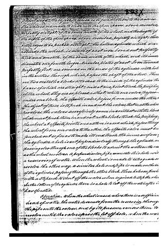
Page 3.
Proposed, the object of which is to give motion to the valves. The valves are made to slide into the open spaces, above described, perfectly airtight, of the same width of the wheel, and the length of the depth of the open spaces, above described, perfectly airtight; their outer edges to be packed airtight. The hollow cylinder which surrounds the wheel, is made of cast iron bored out perfectly true and smooth, of the same width of the wheel, and its inner diameter one fourth larger. Circular plates of cast iron turned perfectly flat, are screwed on the ends of the cylinder with holes in the centres through which passes the shaft of the wheel. There are two metallic blocks attached to the inside of the cylinder the faces of which are straight, and at one point touch the periphery of the wheel. They are so placed as that, while one valve passes under one block, the opposite valve passes from under the other. The object of these is to push in and out the valves, that is, as the wheel revolves, the valves successively come in contact with the blocks which must push them in and out, as the blocks touch the periphery, the wheel at opposite points, and as there is a row which passes through the wheel from one valve to the other, the opposite valve must be pushed out so far as to make its end touch the inner surface, the cylinder. A hole is cut perpendicularly through the cylinder, and passing also through one of the blocks to admit the water on the one as the wheel revolves, a perpendicular pipe connects this hole with a reservoir of water, where the wheel is made to rotate and so reverse the other way, a similar hole and pipe is made on the side of the cylinder passing through the other block. These holes are provided with a stopcock to shut off the water when required to stop the wheel. In the bottom of the cylinder there is a hole to let off the water after it has operated.
Operation—When the wheel is used where there is a sufficient head of water, the water descends from the reservoir through the pipe on to the valves, and by its pressure causes them to revolve until the valves pass the let off hole, when the water
Page 4.
is discharged. But when the supply of water is small, and it is desired to increase the power of the wheel, the water descends from the reservoir onto the valves of the wheel, as before described, and after it passes from the let off hole into the reservoir, it is forced out by a forcing pump, which is worked by the wheel, and at the same time produces a vacuum under the valves. When it is applied to boats or railroad cars, the water is raised into a reservoir by steam or manual power; it then descends into the perpendicular pipe on the valves as before described, and out through the let off hole into the reservoir, and then forced up into the reservoir above mentioned, at the same time producing a vacuum under the valves.
The dimensions of the wheel and its several parts can be varied according to the power required, and the fancy of the builder, provided the principle be retained.
What I claim as new, and as my invention, and for which I ask Letters Patent, is the construction of the described water wheel, the principle of hydrostatic pressure as applied to water wheels, and the producing a vacuum under the valves of the wheel, by forcing pumps, and also the principle of propelling railroad cars, and boats or vessels, by water power.
In testimony that the above is a full and exact description of the construction and operation of my invention, I have hereunto subscribed my name this 27th day of September, in the year of our Lord 1834.
Witnesses
Samuel Hollingsworth
Barnabas Waterman
Garet S. Hermance
(Exd
d/g)
12416 (1834)
Published accounts: journal notice
Notice in the monthly list of patents, with remarks
Journal of the Franklin Institute, new ser., vol. 15 (1835), p. 262 · View the page
34. For Water Wheels; Garet H. Heermance, Coxsackie, Greene county, New York, September 30.
Remarks. This water wheel is "to propel all kinds of machinery, rail-road cars, vessels, or boats," &c. The construction of the wheel is the same with that of some rotary steam engines which we could point out in the books. A circular drum is to be used, the periphery and ends of which are to be perfectly true, and a wheel, with valves, or buckets, is to be made to revolve in this drum; this wheel, and its valves, must fit perfectly tight, but revolve freely between the heads, and the valves are to slide, air tight, but freely, into openings made in the wheel to receive them. A rod connecting two opposite valves passes through the wheel, so that, as one slides into the space prepared for it, the other is protruded. Two blocks, or stops, on opposite sides of the drum, and about one-third of the circumference of the circle apart, touch in one point, the periphery of the revolving wheel, and serve to retract and protrude the valves. Water, under a sufficient head, is to be let in, to act upon the valves, or buckets, and is to be discharged at another opening. In rail-road engines, &c., where there is not a sufficient head of water, it is to be pumped up by hand, steam, or otherwise, into a reservoir, and used over and over again. All who know anything of mechanics, will now be ready to exclaim, "Stop there, we have heard enough;" and as we think so too, we will merely add the claim, without a word of comment. "What I claim as new, and as my invention, is the construction of the above described water wheel, on the principle of hydraulic pressure, as applied to water wheels, and the producing a vacuum under the valves of the wheel, by forcing pumps; and also the principle of propelling rail-road cars, boats, or vessels, by water power."
About this record
- Patentee
- DATAMP
- Date
- the Name and Date index of patents, DATAMP, USPTO records
- Invention
- DATAMP
- Listed in
- the Name and Date index of patents, DATAMP, USPTO records, Jim Shaw's X-patent list, the Journal of the Franklin Institute, Burke's List of Patents (1847)
- The Franklin Institute's journal spells the name differently.
- Burke's 1847 Patent Office list gives the same patent.