

Drawings and documents
National Archives restored drawings: drawing
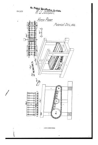
William G. Johnston's Patent Drawing for a Method of Producing Horse Power

National Archives, Restored Patent Drawings (Record Group 241) · Full-size scan at the National Archives · Catalog record
Show the text on the drawing Hide (189 words)
Words on the drawing as machine-read by the National Archives; not checked. Useful mainly for searching.
185. MECHANICAL MOTORS. / Horse-Powers, / CLASSIFICATION g Johnston / Engineering Hore Priver / Vol. is ps.467 / Patented bex. 4. 1834. / Treads. / DIVISION / Fig.3 / Horse Power. / 12 / ORE / la / Juli / la / Ju / J.y. / 600 / LA / Ty.6 / THE / in / Jiy.8 / Jig.5 / Jig.2. / Preferences. / a.a.a.a frame / b.b. large heads. / C shaft. / d.d mall headand haft. / e.e.e.e.e.do. friation wheels. / g.g.g.g. shafts / h wooling platform. / i.i. endless chain. / K.K.K.K.Ne screwfolts / d.l.l.l.i cogs. / m trundle headand pulley. / n Se. iron pla tes orfacing forrailway. / Tig.1. / Tig. 1. Perspective view of the Horse Power. Jij.2. Section Sig.3 Top viewofa part / Patent affice 30th September 1841. / Hicschmann fait / of the revolving Platform. Jij. s Lide blow showing the manner offastening the chain. / made under the direction of / of Patents in can formity with act of 320 march 1837. / Fig. Iron facing forming a zailway marked n.n. Ve: Fig. Fig 7 the chain. Fig. showing the inside / of the revoloing platform. Fis.g friction wheel c. / Hymyh Sumath / Commissioner of Patents
USPTO scan
The patent as scanned by the USPTO
-
 Page 1
-
 Page 2
-
 Page 3
-
 Page 4


U.S. Patent and Trademark Office · Google Patents
Show the transcription Hide (717 words)
Machine transcription (LightOnOCR) of the pages as scanned by the USPTO, most of them the handwritten copies made when the records were restored after the 1836 fire. Not checked; it can misread handwriting, so compare it with the scan.
Page 1.
8432X
No Printed Specification Available
W. G. Johnson
Horse Power.
Patented Oct. 4, 1834.

U.S. CO. N.Y. (OSBORNE'S PROCESS)
Page 2.
William G. Johnston, Bridgetown N. J.
Letters Patent.
The Schedule referred to in these Letters Patent, and making part of the same, containing a description in the words of the said William G. Johnston, himself of his improvement, being a machine for propelling machinery, called Johnston's inclined plane Horse power.
Be it known that I, William G. Johnston of Bridgetown in the county of Cumberland, and State of New Jersey have invented a new and useful improvement in the useful arts; being a machine for propelling machinery, called Johnston's inclined plane Horse power, which is described as follows.
I make a frame, say nine feet long, two feet wide, (or of any convenient size) at each end and within this frame, are placed two heads or cylinders made in the following manner. — Take a piece of wood say twenty inches in diameter, two inches thick, with the periphery of the whole made there, from the bottom down to a new inch in thickness, and bander with iron. Two of these heads or cylinders are placed on a shaft so as to reach the outer edge of the revolving floor horse after described, at the other or lower end of the frame, I make two similar cylinders, but of ten inches diameter, of wood, iron or any suitable materials; they are placed at the end and within the frame before described, on a line so as to form on the periphery of the wheels or cylinders an inclined plane at an angle of about ten degrees, or as may be convenient; upon the inner side of the inclined plane, and at proper distances a partition
Page 3.
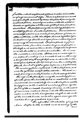
friction wheels are placed of four inches diameter, or of any convenient size; these are placed one on each end of a shaft, secured by boxes to a plank forming the inclined plane, running on a line with the wheels or heads or cylinders at the ends of the frame first described. The parts forming the revolving platform, or stepping floor, I make as follows:—Two continuous or endless chains are made from pieces of iron, or other material, with the strips joined together by links forming joints or hinges, from inches long each, or as may be convenient, the spare plank, say four inches wide, from ten inches long, and of proper thickness, and secure them to the endless chains by screws or rivets, parallel and close to each other, so as near the middle and inside. I place one or more cogs in each plank working in a tumbler head on the end of a horizontal shaft across the frame, and on the outer ends of each plank I put pieces of iron the width of the plank, bent at right angles to form a water rail. The revolving floor is placed within the frame, and over the cylinders and friction wheels.—The lead or nail passing over the friction wheels and cylinders.
The cogs in the plank forming the revolving floor, operate upon the tumbler head or wallower which is secured immediately beneath the floor motion being given to the inclined revolving floor, by the power of the animal leading thereon, in the manner of common inclined horse wheels. This communication is also given to the horizontal shaft in the ends of the tumbler head; and this again conveys the motion to any machine required.
For a further illustration of my invention, I refer to the model now remaining of the
Page 4.
same, deposited in the patent office.
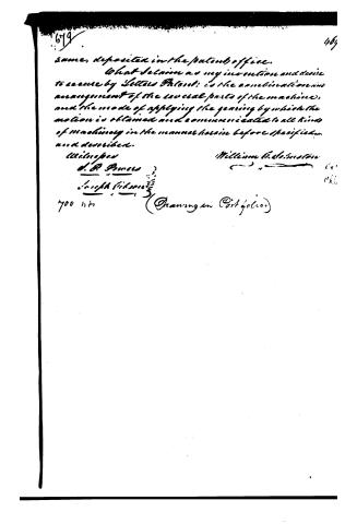
What I claim as my invention and desire to secure by Letters Patent; is the combination and arrangement of the several parts of the machine, and the mode of applying the gearing by which the motion is obtained and communicated to all kinds of machinery in the manner herein before specified and described.
Witnesses
William B. Johnston
J. R. Powers
Joseph Gibson
700 lbs
(Drawing in Portfolio)
Published accounts: journal notice
Notice in the monthly list of patents, with remarks
Journal of the Franklin Institute, new ser., vol. 15 (1835), p. 314 · View the page
6. For a Horse Power; William G. Johnston, Bridgetown, Cumberland county, New Jersey, October 4.
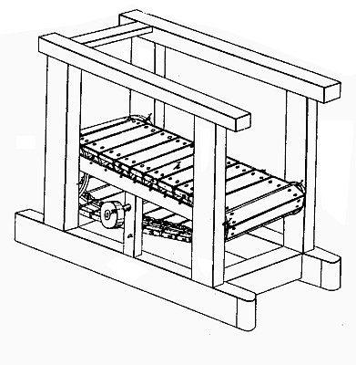
Remarks. An inclined movable floor is formed with slats of timber, connected by endless chains, which pass over cylinders at each end of the machine, friction wheels being used to sustain it; all these parts are combined together in a manner differing so little from what has been frequently done, that it would be a difficult, and at the same time a useless, task to point out the novelty of the contrivance; the patentee has not attempted it, but claims "the combination and arrangement of the several parts of the machine, and the mode of applying the gearing by which the motion is obtained and communicated."
DATAMP: illustration
Illustrations from DATAMP

DATAMP (Directory of American Tool and Machinery Patents), via the Internet Archive · Archived DATAMP page
About this record
- Patentee
- DATAMP
- Date
- the Name and Date index of patents, DATAMP, USPTO records
- Invention
- DATAMP
- Listed in
- the Name and Date index of patents, DATAMP, USPTO records, Jim Shaw's X-patent list, the Journal of the Franklin Institute, Burke's List of Patents (1847)
- Burke's 1847 Patent Office list gives the same patent.