

Drawings and documents
National Archives restored drawings: drawing
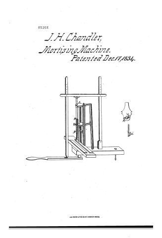
J.H. Chandler's Patent Drawing for a Morticing Machine

National Archives, Restored Patent Drawings (Record Group 241) · Full-size scan at the National Archives · Catalog record
Show the text on the drawing Hide (117 words)
Words on the drawing as machine-read by the National Archives; not checked. Useful mainly for searching.
144, WOOD WORKING MACHINES. / Mortising, Chisel Cutters. / J.H. CHANDLER'S / 75°F / Morticing machine. / Patented Dec. 19th 1834. / CLASSIFICATION / 8530-x / DIVISION. / y.y. The piston. svoore / t. The handle wring / e Spring. / i La leral ohisel / k. Tooth working in groove / This is to certify that this drawing was made under the / dreation of the Commissioner of Patents in conformity to the / provision of the Act of 3 of Mar 1837. Sect 1st pom and in / conformity noith the specification on which letters Patent / mere granted th the Said IH Chandler 17th Dee 1834 / and recorded anew on the 14 th day of April 1898 / Commissionery of Patents
USPTO scan
The patent as scanned by the USPTO
-
 Page 1
-
 Page 2
-
 Page 3
-
 Page 4
-
 Page 5
-
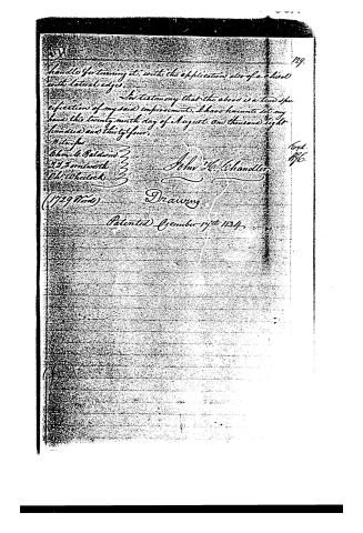 Page 6


U.S. Patent and Trademark Office · Google Patents
Show the transcription Hide (1,605 words)
Machine transcription (LightOnOCR) of the pages as scanned by the USPTO, most of them the handwritten copies made when the records were restored after the 1836 fire. Not checked; it can misread handwriting, so compare it with the scan.
Page 1.
8530X
J. H. Chandler,
Mortising Machine.
Patented Dec. 17, 1834.

A.M. PHOTO-LITHO. CO. N.Y. (OSBORNE'S PROCESS)
Page 2.
July 1834
John H. Chandler, Worcester, Massachusetts.
The schedule referred to in these Letters Patent, and making part of the same containing a description in the words of the said John H. Chandler himself of his Improvement in the construction of machines for Morticing.
To all People to whom these presents shall come,
Greet.
Know that I, John H. Chandler, of Worcester, in the County of Worcester, and Commonwealth of Massachusetts, do hereby declare that I have invented a new and useful improvement in the construction of Machines for Morticing, and that the following is a full and exact description of the same as invented or improved by me.
The Machines heretofore used for making Mortices, have been attended with three difficulties. The piston or shaft holding the Chisel has been so imperfectly supported or guided, that it was liable to be removed from its right position, thereby making the Mortice irregular or out of square, and in order to remedy this evil, the piston has been so closely confined that the operation of the Machine has been greatly embarrassed by too great friction. Another inconvenience has also arisen from the use of Common Chisels, which leave the chips in the Mortice, and much time is required in removing them. All these inconveniences are removed by constructing the Machine after the manner proposed by me which is as follows:
The frame of the Machine may be constructed of wood or iron, or any suitable material. My Machine is partly of firm hard wood and partly of iron. A plank of convenient dimensions comprises the foundation of the frame. Near the front end of the plank are mounted three parts of wood, the feet of the two front ones are secured into the plank but
Page 3.
The third one stands back between them, and is turned into it. The parts are firmly connected by rails, and plates or castings. These castings are of a triangular form, and connect the parts at the angles. One of these is near the top, and the other is placed about one third of the distance from the top downwards towards the bottom. The front end of these triangular pieces of iron, are circular, projecting out in front of the two front parts, which is near them. Each of them at the end, in the center, is near the end as well as near. Through these holes passes the piston which holds the chest in a socket at the lower end. The piston is movable up and down through the holes made in the castings mentioned above. On one side of the piston, and half the length of it, is cut a groove. On the upper side of the lower plate or casting, and directly back of the piston, is a spring, the back end of which is made fast to the casting, the other end is made forked, the legs of the fork passing each side of the piston, partly beneath the foot of the spring, is an iron ring passing round the piston, and on the inside of it, is a tooth, or projecting piece of iron fitted to move in the groove on the piston. This ring has two stems or handles attached to it, for the purpose of turning the piston. The ends of the handles as they pass around under the spring are made to fall into a notch on the right hand side of the casting. A little below the lower casting is framed into the foot, a narrow rail, for the purpose of running a screw. Below this, close down on the plank is another, to assist in holding the parts together, and confining them to it. In front of the foot of the two front parts, is firmly confined a plank resting upon, and attached to the foundations of the frame or machine, and raised by means of a bolt. Upon this, or of pieces are two slides parallel to each other, and movable at pleasure with slats and screws to confine them. On the back slide is mounted a standard extending up to the screw, passing through the narrow
Page 4.
127.
as mentioned above and confined to it, passing through the foundation, or foot piece and slides, on the right hand side, and accommodated with a screw to confine it at pleasure. U. an iron holder with a head, on the front side of it. Back of the third foot, are firmly set two short standards, with a space between them. In this space is fastened a pin, the lower end of a shaft, which extends up somewhat higher than the foot, in the centre and directly underneath the roof piece, is firmly set a lever, attached to this at the end in a mortice, by a pin. V. a lever with a handle turned on the end of it. Near the end of this lever towards the machine, is fastened by a hinge, another shaft of the same size and light of the other. From the top of this shaft upwards, are inserted at short distance apart fine holes, attached to the upper end of this shaft, is another lever, by means of mortices and pins at the end, on the under side of this lever, and at a short distance from the front end, is placed a hinge, to which is attached the upper end of the piston. This lever is movable up and down on the fine holes. The chisel is accommodated with two lips which, in addition to making the sides of the mortice smooth, does, by pressing the chips between them, bring them out of the mortice. The machine may be operated upon a common workbench it being confined to it by means of a belt—
Explanation of the Drawing
A. Bank or foundation of the Machine. B. Roof piece. C.D. two foot posts. S. foot back of the two front ones. K. triangular piece of iron, for connecting the posts, and guiding the piston. M.M. another similar piece for the same purpose. O. end of the forked spring. T. iron ring with a stem or handle for turning the piston. O.S. piston holding the chisel. G.G. groove in the piston. g. holder to prevent the piece, while morticing, from rising. p. Standard moved at the top by the screw. S. S.S. chisel inserted into the lower end of the piston and slides between which the piece to be morticed is placed. S.
Page 5.
Standards inserted into the foundation of the machine, at a right shaft movable on a pin at X. L upper lever movable on a pin at each end, by front shafts W. Lever connected by a pin to the lower, with the plank A 2 bolt or screws to confine the machine to the back of handle of the lever.
Operation of the Machine
The operator takes the piece to be mortised in his left hand, and lays it on the end pieces on the left hand side of the piston between the two slides a a. He then with his right hand takes hold of the lever w. at the handle v, and by raising it, the shaft being connected to it by a hinge and the upper lever L to the shaft by a pin and the piston being connected to the lower lever moved also. He then moves the piece under the chisel where the mortise is to be made. He then adjusts the slides and Standards, by confining them with the screws in such a position, as will bring the chisel exactly between the gauge strokes of the Mortise. He then brings his hand against the Standard, to feed the chisel, and then bears down upon the lever at v, and the chisel is made to cut down the depth required, and by means of the lips or lateral edges of the chisel, the chips are brought out of the Mortise. This operation is repeated until the mortise is extended to the desired point in one direction. When the operator turns the piston half round, and with it the chisel, to present the chisel in a proper manner for the other end of the Mortise. This operation is performed by taking hold of the stem t, in the ring which passes round the piston, and causing it round upon the opposite side when it falls into a notch in the triangular casting R, and is confined in its proper position by the lips of the forked spring c. The piston is moved round by the stem or handle t, by means of the tooth attached to the inside of the ring, and being in the groove b b, of the piston, all I claim as my invention or improvement, is the groove in the piston, with the forked spring, and ring with tooth and
Page 6.
handle for turning it, with the application also of a chisel to the lateral edges.
In testimony that the above is a true specification of my said improvement, I have hereunto set my hand the twenty ninth day of August one thousand eight hundred and thirty four.
Witnesses
Chas. L. Baldwin
13 Hornsworth
Chas. Wheelock
John H. Chandler
(1729 Words) Drawing
Patented December 17th 1834.
Published accounts: journal notice
Notice in the monthly list of patents
Journal of the Franklin Institute, new ser., vol. 15 (1835), p. 143 · View the page
588. Mortising machine.-J. H. Chandler, Worcester, Mass.
Published accounts: journal notice
Notice in the monthly list of patents
Journal of the Franklin Institute, new ser., vol. 15 (1835), p. 144 · View the page
617. Hemp dressing machine.-Chandler E. Potter, Portsmouth, N. Η.
Published accounts: journal notice
Notice in the monthly list of patents, with remarks
Journal of the Franklin Institute, new ser., vol. 16 (1835), p. 22 · View the page
18. For a Mortising Machine; John Hassett Chandler, Worcester, Worcester county, Massachusetts, December 17.
Remarks. The patentee says, "All I claim as my invention, is the groove in the piston, with the forked spring and ring with tooth and handle for turning it, with the application also of a chisel with lateral edges." Excepting in certain unimportant points of arrangement, there is but little difference between this and other mortising machines previously patented; even the chisel with lateral edges has been before applied, and is not, therefore, the legitimate subject for a claim.
About this record
- Patentee
- the Journal of the Franklin Institute, Journal
- Date
- the Name and Date index of patents, USPTO records, Jim Shaw's X-patent list
- Invention
- the Name and Date index of patents
- Listed in
- the Name and Date index of patents, USPTO records, Jim Shaw's X-patent list, the Journal of the Franklin Institute, Burke's List of Patents (1847)
- The patentee's full name comes from the Franklin Institute's journal.
- Burke's 1847 Patent Office list gives the same patent.